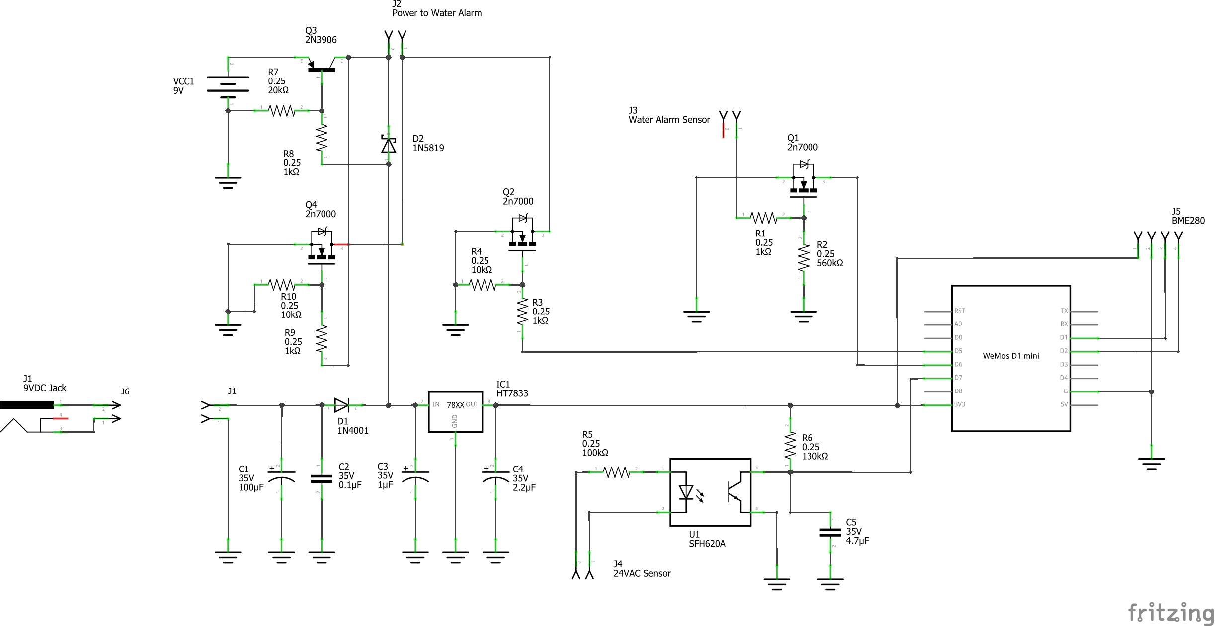
I've developed a smart circuit for the watchdog water alarm (teardown here)and I am ready to have PCBs made up. Before I do so I would like to get everyone's critique and as an amateur I do have a few questions.
My original criteria was to create a smart water alarm that runs on 9VDC to use with home assistant. I also wanted to be able to use a rope sensor instead of the flat metal probes that the stock alarm uses and plug this in via a 3.5mm audio jack. While I was at it I thought it would be nice to have a sensor detect if my HVAC condensate pump fails (through the pump's safety switch) since I will be using the alarm around my furnace to detect leaks from this pump or our whole house humidifier. A remote mute switch, temperature/humidity sensor, and 9V battery dumb-backup were also a must, all run by a Wemos D1 Mini.
Criteria List
- Wemos D1 Mini
- Rope sensor through 3.5mm jack
- Condensate pump sensor - 24VAC HVAC through optocoupler
- Alarm mute
- Battery backup
- Temperature/humidity (BME280)
Questions
I've tested this circuit for a few weeks now and it seems stable but I do have the following questions.
- What type of connector should I use for the 24ACV condensate pump sensor connection? I was thinking of using a 5.5mm x 2.1mm barrel type as I have these laying around. I can only find DC specs and those are up to 12V. Can this be used or what's an alternative suggestion? I have these two parts on hand Option 1 and Option 2. I would prefer a small round connector that could be panel mounted like these two options.
- The resistors used for 24VAC I am using are only rated for 1/4 watt, they don't get hot but should I be using 1/2 watt as I've seen suggested on a few sites?
- Can a standard 3.5mm audio jack handle 9VDC long term as that's what is running through the rope sensor? Here is what I am using (PJ392 stereo female socket jack 3.5 audio headphone connector).
- I did have to use some trial an error with R7(20K) and R2(560K). Usually a standard 10K pulldown resistor has worked well for me with past projects. With this project I was getting some fluctuations with Q3 and Q1 and had to try quite a few values before I came up with what you see. Is this expected with my circuit?
- As this is my first time dealing with AC voltage do I need to do anything different with the PCB trace width? Fritzing's standard size is 24 mil. Is this adequate for the 24VAC or should I go wider?

