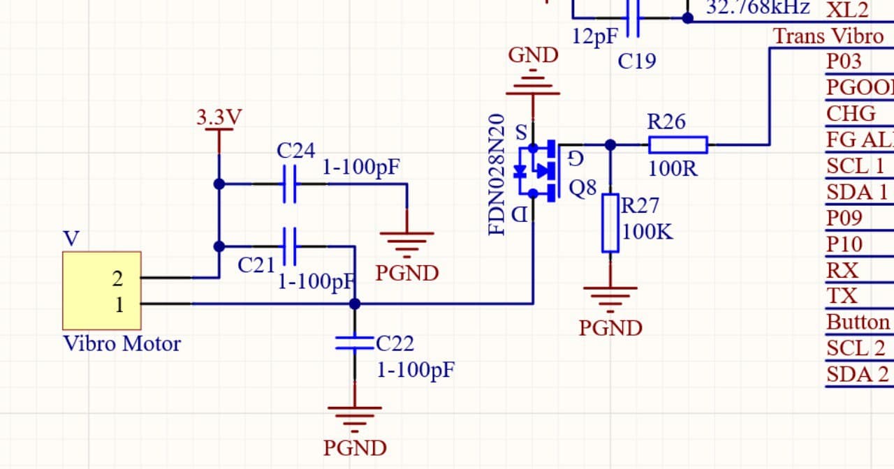
We are using a FDN028N20 n-channel MOSFET for load switching. Load current is 80mA max. and it is controlled via processor's 3.3V pin (NRF52832).
Our schematic:
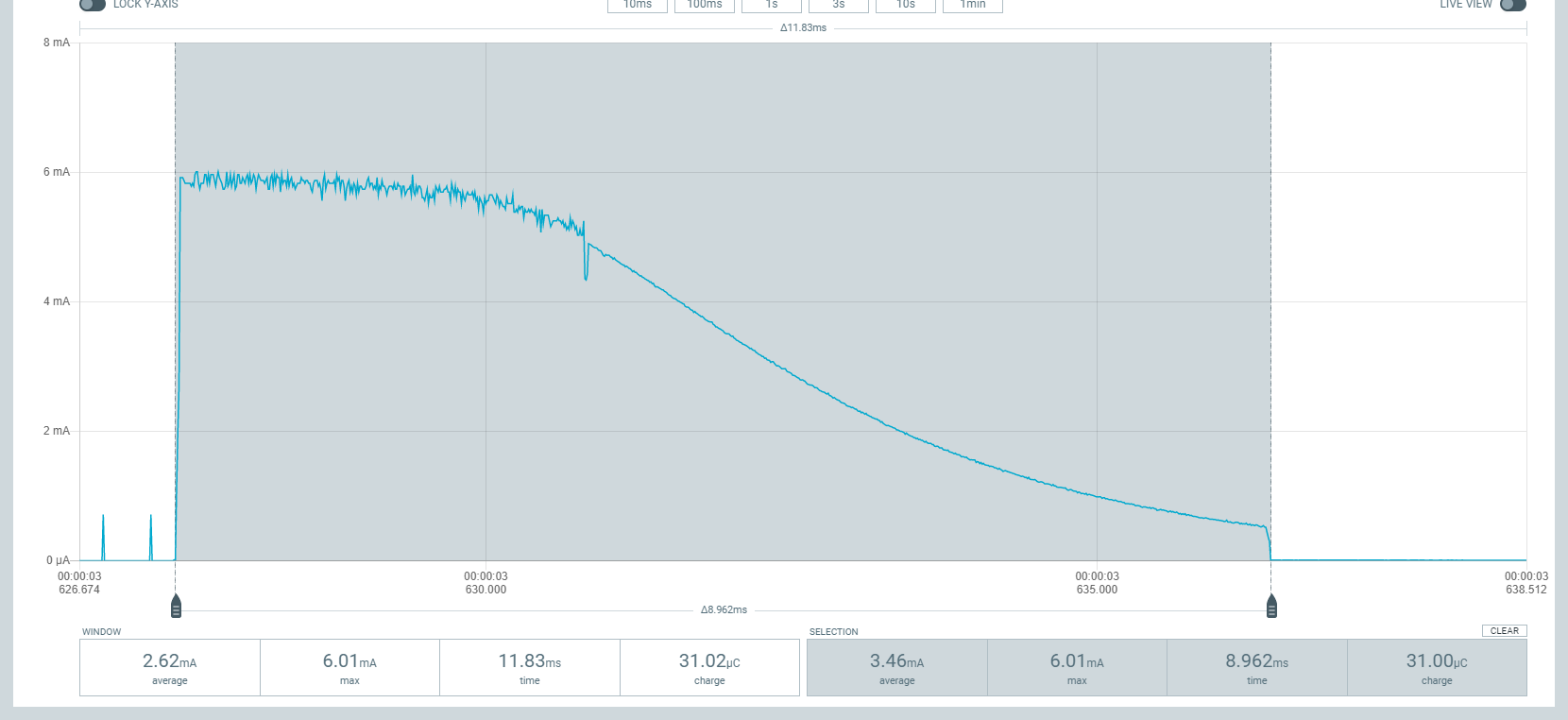
When the MOSFET turns off, I measure 6mA current peaks flowing into the processor pin. We make the measurement using a Power Profiler Kit II. This is expected since the gate behaves as a capacitor, and discharges.
You can see the peak in the screenshot below:
Sometimes these peaks may reach higher values (e.g. 15-20mA). It is said that overall current going in/coming from the pin shouldn't be above ~20mA. (https://devzone.nordicsemi.com/f/nordic-q-a/15800/gpio-sink-current-on-nrf52832/60290#60290).
That's why I am worried that in this design pins may be damaged in the future. I tried to reduce the peak current using a gate resistor, but surprisingly the peaks increased in frequency and sometimes even in amplitude (we tried various gate resistors - 100Ω, 1000Ω, etc).
Can someone please explain to me why the gate resistor doesn't reduce amplitude of peaks and how to protect the processor pin?
Note: I tried the same with other loads and observed the same behavior. This question is not about driving a motor with PWM, but a general problem we observe on other loads too (LEDs etc.).
Edit:
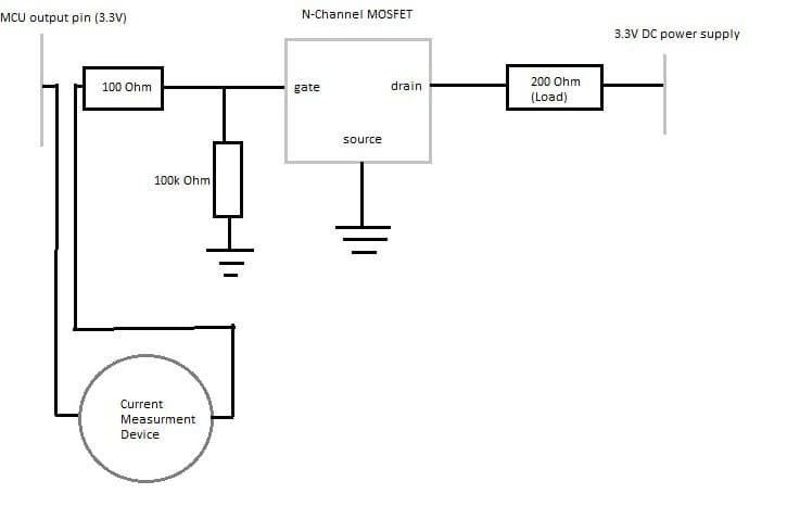
I made the same test with another load (resistor). See the circuit below:
As you can see there is no motor here, and I suppose there shouldn't be any EMF related issues here with a resistor as a load.
The processor switches its output state every 5 seconds (5 seconds high, 5 seconds low) infinitely.
You can see the measured current below:
As you can see, these peaks happen all the time. I tried removing the gate resistor, and had the same result.


