0
\$\begingroup\$

I have a lab for a circuits class and in it we are building an RC series circuit with a square wave input. I am using a function generator to produce a square wave at 50Hz, period = 20ms, Amp = 500mV, Offset = 500mV. I am to measure the output voltage across both the resistor and capacitor.

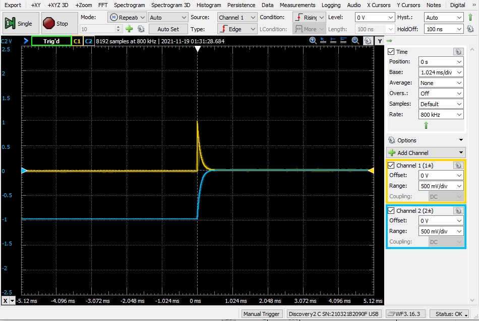
The resistor is 10k-Ohm and the capacitor is 10nF. I know at T = 0 the resistor drops all the voltage and the capacitor drops effectively none, and that over 5 TC the capacitor charges and the current through the resistor lowers. So the graph for the resistor should be a jump to source voltage then taper off to 0V while the capacitor should start at 0V and ramp up to source. However, When I plug in my O-scope, I am getting the resistor behaviour as expected, and the shape of the capacitor waveform is as expected, but starts at -1 V and ramps to 0V. So it looks like on the O-scope that at 5TC neither component is dropping any voltage.

I have read some previous similar questions and applied some of the solutions found there to no avail, such as: I have checked for DC coupling and have verified the circuit is getting the input by using the O-scope to check the function generator output directly, as well as measuring the component voltage with a Fluke.
How do I get the capacitor to show starting at 0V and ramping to 1V?

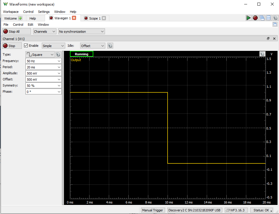
Here is the input from the function generator: Screenshot of function generator waveform
Here is the output measured by the O-scope: O-Scope output
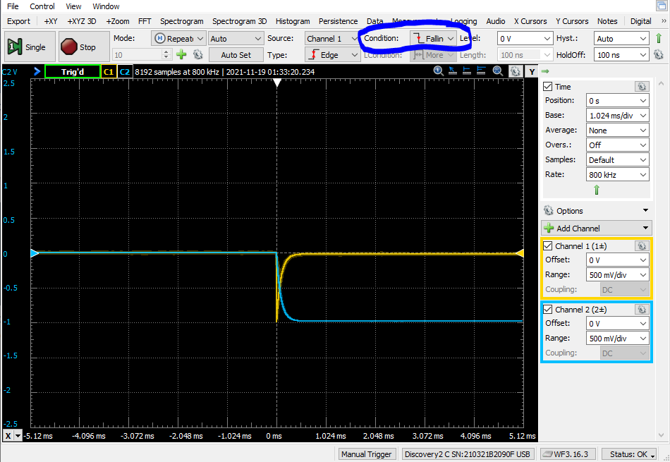
If I change the condition to falling edge, the waveforms overlap in a behavior mimicking what I anticipated, but goes from 0 to -1V, which I don't understand since the input voltage is never negative (and when changing the function generator input to a rising squarewave, the O-scope waverforms don't change). Falling Condition
\$\endgroup\$
2
  • 1
    \$\begingroup\$ Can you provide a schematic of your test-setup? Please show how you connected the probes. \$\endgroup\$
    – Rens
    Commented Nov 19, 2021 at 7:50
  • \$\begingroup\$ Tune the scope to see, at least, a whole period of generator ... \$\endgroup\$
    – Antonio51
    Commented Nov 19, 2021 at 8:05

1 Answer 1

0
\$\begingroup\$

I am getting the resistor behaviour as expected, and the shape of the capacitor waveform is as expected, but starts at -1 V and ramps to 0V.

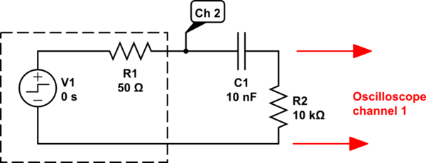
A different point-of-view...the capacitor starts at 0V before the square-wave edge occurs, rather than -1V. In this state, no current is flowing, since the voltage across the resistor is 0V as measured by the oscilloscope.

So naturally you ask, "where does the -1V transient come from when the square wave switches?". Just before the transient occurs, voltage across the resistor is 0V but the function generator output is at +1V. The capacitor is charged with the difference (it is charged with 1V): its function-generator-end is at +1V, while its resistor-end is at 0V.
Now the square wave edge occurs very fast, and the capacitor's function-generator-end drops from +1V to 0V. The capacitor's charge tries to dump by causing current to flow. This current path includes the 10k resistor, but it also includes the function generator's internal 50 ohm source resistance. Since 10k > 50 ohms, almost all of the 1V change appears across the 10k resistor...if you were to look very closely, you'd see that the resistor voltage drop is actually -0.995V.
From there, the transient exponential rise to 0V proceeds while the capacitor charge dumps out.

schematic

simulate this circuit – Schematic created using CircuitLab


How do I get the capacitor to show starting at 0V and ramping to 1V?

OP's waveforms show that the oscilloscope trigger is from channel 1. Channel 2 is connected to function generator output, and should be the trigger source instead of channel 1.

When looking at the transient voltage across the resistor on channel 1, there are two transient directions (one going up, another going down). This is mightily confusing to the trigger slope direction (+/-).
If you trigger from the function generator waveform on channel 2, trigger edge direction is unambiguous, and you should have no trouble triggering on rising edge versus falling edge.

One other point...You might see on close inspection that function generator output is not entirely square-edged. This is caused by the 50-ohm internal resistance. This effect would be more apparent if you used a smaller load resistor than 10k.

\$\endgroup\$
1
  • \$\begingroup\$ Thank you. Your answer was key to getting my simulation to work. Putting the trigger on CH2 made all the difference in stabilizing the output. Also, your explanation of circuit operation was very helpful. Using this information, I was able to complete this part of the lab in a way I feel confident. \$\endgroup\$ Commented Nov 22, 2021 at 22:26

Your Answer

By clicking “Post Your Answer”, you agree to our terms of service and acknowledge you have read our privacy policy.

Not the answer you're looking for? Browse other questions tagged or ask your own question.