1
\$\begingroup\$

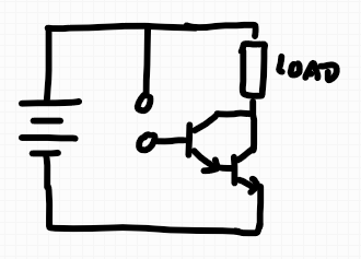
I remember a circuit from back in my earlier days of playing with Arduinos and electronics that would light up an LED when two leads are touched with a poor conductor (e.g. a finger).

I don't remember the specifics, but I remember it involving almost nothing but two transistors, an LED, and some kind of power source. It was simple enough to solder it all together without even a breadboard and carry it to school in a backpack to get extra points with my physics teacher, heh.

I've been able to find similar circuits with some rough googling but none of them seem to be it; there is a single mosfet implementation, and a few that use other ICs that I'm not quite interested in. I'm mostly trying to remember the name of the circuit, which I remember being kinda unique (I want to say it was some engineer's name, and I think it ended in an -ie sound, like -ixie or -itsy circuit or something).

Thanks!

Update: I found this circuit diagram in the source for one of my REALLY old personal websites. I guess I really liked this circuit! Of course the image is helpfully labeled "circuit.png", but I am 99.9% certain this is the circuit in question.

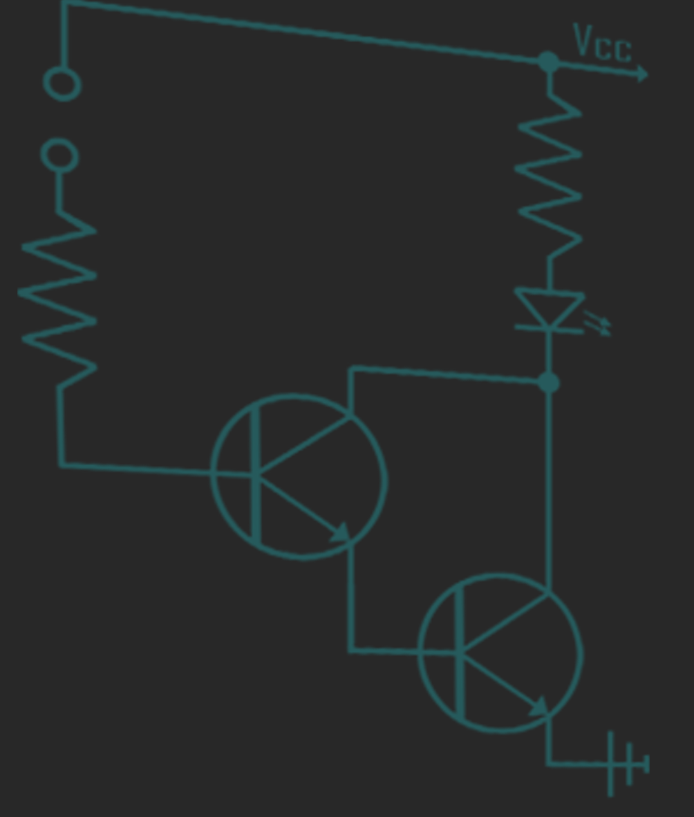
a hand-drawn / rendered circuit diagram of the mystery touch-sensor circuit

\$\endgroup\$
4
  • 2
    \$\begingroup\$ Is "Darlington" the name you were looking for? \$\endgroup\$
    – ocrdu
    Commented Nov 28, 2021 at 21:20
  • \$\begingroup\$ That's just two NPN transistors in a Darlington pair configuration. Is the word Darlington? Another similar configuration with NPN and PNP transistor would be Sziklai pair. \$\endgroup\$
    – Justme
    Commented Nov 28, 2021 at 21:21
  • \$\begingroup\$ shawkins, I remembered something well enough that I could find a very early example. It's here. 1971. Two transistors. But one is a JFET. Anyway, these kinds of things date way back. Just FYI. \$\endgroup\$
    – jonk
    Commented Nov 28, 2021 at 21:52
  • \$\begingroup\$ Thanks so much everyone! Darlington pair is what I was looking for! \$\endgroup\$
    – shawkins
    Commented Nov 28, 2021 at 22:32

2 Answers 2

1
\$\begingroup\$

You're likely thinking of a Darlington Pair, which is a high-gain cascade of two BJTs that gives very high current gain:

enter image description here

The two transistors are connected in such a manner that a tiny current passed through the touch contacts will be multiplied by the transistor beta (a measure of its current gain), and then multiplied again by the beta of the second transistor, resulting in an impressive current gain able to at least weakly light the LED from leakage through the person touching the sensor.

For example, the beta of a 2n3904 (a common NPN BJT) is on the order of 100, meaning that you can get 1 mA of load current (enough for a dim LED) from around 100 nA of leakage.

Note to address the 'mosfet' tag on the question - this exact topology is a bit harder to realize with pair of MOSFETs because FETs are voltage-controlled devices with very insulated gates. Rather than having a finite current gain, a FET sensitive to the tiniest bits of charge deposited on its gate electrode, meaning that it'll float around and may flicker on and off even when the touch sensor is not touched.

However, TimWescott's answer mentions an alternate topology that uses a MOSFET to realize a similar touch sensor function using a single FET in a way that doesn't suffer from the above issues.

\$\endgroup\$
1
  • 1
    \$\begingroup\$ Wow, thank you! Darlington pair is what I was looking for, but the extra context here is really great. \$\endgroup\$
    – shawkins
    Commented Nov 28, 2021 at 22:32
2
\$\begingroup\$

Yes, the circuit you have pictured would do as you describe. The two transistors form a darlington pair, which acts like a single transistor with current gain equal to the product of the current gains of the two constituent transistors.

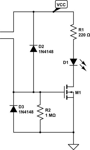
Another circuit that would work, after some fiddling with component values, would be the one below. The N-channel FET acts like it has "infinite" current gain; R1 limits current to the LED (so size it for VCC). R2 keeps the thing from turning on from passing electrons (and makes sure it turns off). D2 and D3 are sorta-kinda optional, but they protect the gate of M1 from static electricity (they wouldn't be a bad thing to add to your circuit, for longevity in dry climates).

The only important bit is to choose a FET for M1 that's compatible with VCC -- any old FET will do if VCC is 12V, but if VCC is 9V or 5V you probably want a "logic level" FET.

schematic

simulate this circuit – Schematic created using CircuitLab

\$\endgroup\$

Your Answer

By clicking “Post Your Answer”, you agree to our terms of service and acknowledge you have read our privacy policy.

Not the answer you're looking for? Browse other questions tagged or ask your own question.