1
\$\begingroup\$

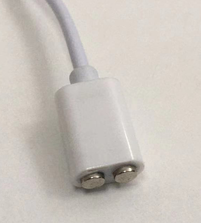
I'm working on a low voltage DC consumer product that specifies using a specific magnetic charge cable on the 5V input instead of a regular USB connector. See image:

magnetic charge cable

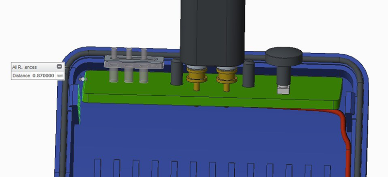
We started out assuming the cable wasn't symmetrical and there must be a positive and ground that could only fit one way, so we planned to just use a corresponding positive and ground pin on the PCB power input. See image:

pcb connector pins

But later we found the cable is in fact symmetrical, so the user could attach it in an orientation where the positive and ground connections could be swapped. So, we can't just assume to have a static positive and ground pin as shown in the pictures, it seems we need a way to sense upon connection, which pin is positive and which pin is ground and design our circuit to handle it either way.

positive-ground

Are there IC's we could use to help handle this? Some other approaches to the circuit design?

Thank you!

Note: all the images here are my own.

\$\endgroup\$
6
  • 5
    \$\begingroup\$ A bridge rectifier? \$\endgroup\$
    – Kartman
    Commented Dec 3, 2021 at 6:24
  • 1
    \$\begingroup\$ If you can't handle the voltage drop of a bridge rectifier, make a bridge rectifier using those active-diode things that have like 20 mV drop. \$\endgroup\$
    – Hearth
    Commented Dec 3, 2021 at 6:25
  • 2
    \$\begingroup\$ We started out assuming the cable wasn't symmetrical ... always assume that the user will find a way to plug in backward \$\endgroup\$
    – jsotola
    Commented Dec 3, 2021 at 6:28
  • \$\begingroup\$ Look at the USB C dedicated parts, they should have something useful since the problem is the same. Or make a dual half-bridge to switch the polarity arount \$\endgroup\$ Commented Dec 3, 2021 at 6:45
  • \$\begingroup\$ @LorenzoMarcantonio No they don't. The USB-C pinout is such that VBUS and GND is never swapped. \$\endgroup\$
    – Klas-Kenny
    Commented Dec 3, 2021 at 7:09

2 Answers 2

2
\$\begingroup\$

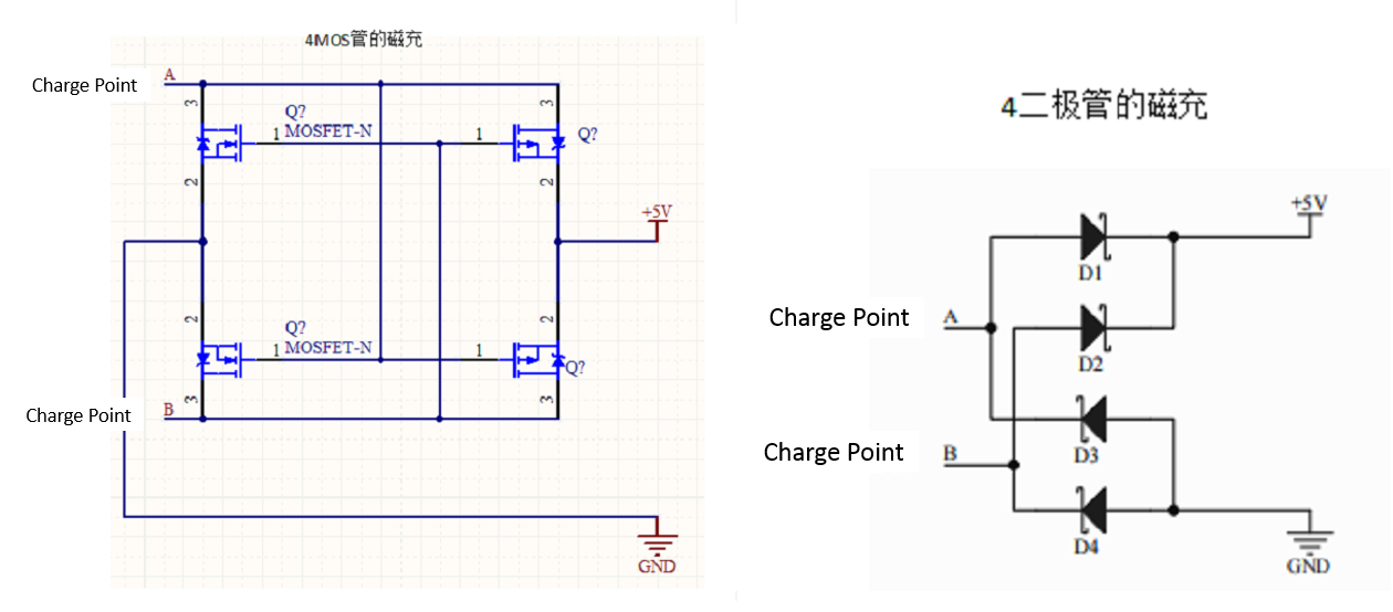
Seems the below two circuits are two ways to handle this, using either four MOSFETS or four diodes, with the MOSFET solution preferred as it results in a lower voltage drop.

mosfets-and-diodes

\$\endgroup\$
4
  • \$\begingroup\$ Onsemi and mps have such rectifiers. Intended usage - PoE \$\endgroup\$
    – TQQQ
    Commented Dec 3, 2021 at 11:44
  • \$\begingroup\$ Bob Jordan - Hi, As required by this site rule, when you include something in an answer (e.g. photo, image or text) which isn't your own original work, you need to properly reference (cite) it. Those images seems to have come from somewhere else, so can you please edit your answer and add a link back to the original web pages (or add equivalent details if the source was a book e.g. title, author(s), publisher, edition and page number). Thanks. \$\endgroup\$
    – SamGibson
    Commented Dec 3, 2021 at 15:12
  • \$\begingroup\$ @SamGibson the images are my own screenshots and pictures, will edit and include a note claiming them \$\endgroup\$
    – Bob Jordan
    Commented Dec 3, 2021 at 15:53
  • \$\begingroup\$ @BobJordan - Thanks for the update. In that case, if you didn't create the schematics in this answer originally, you should credit the source of the original schematics (even if you took the screenshots of them). Otherwise everyone could claim ownership of screenshots of any other source :-) I realise identifying the original source that may be difficult, e.g. if the schematics have been on your hard drive for a while, but please try to indicate the original source (or add an explanatory note, if that's not possible). Thanks. \$\endgroup\$
    – SamGibson
    Commented Dec 3, 2021 at 16:06
2
\$\begingroup\$

Put a magnet in your product that "helps" the user "fix" the cable in the right orientation. If "correctly" aligned, the connector won't flip-off because the magnetic alignment of the two parts will physically enhance the electrical connection. If the alignment is incorrect, the two parts will automatically disconnect unless someone is holding them closed.

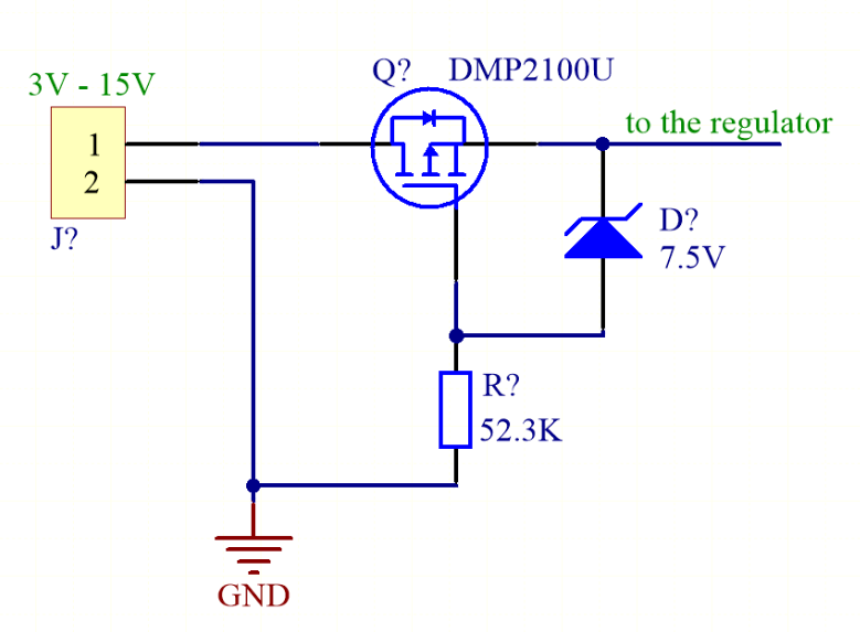
Then, as a final circuit protection feature use this: -

enter image description here

Image taken from here, another SE question/answer. If the incoming supply is correct, the P channel MOSFET turns on and allows normal operation. If the incoming supply is incorrect then the bulk diode in the MOSFET does not allow conduction and, due to incorrect gate-source voltage, the MOSFET will not turn on.

Or, just use the above circuit and forget about the magnet and let users figure out how to orientate the connector themselves. The important thing here is circuit protection (as I see it) AND, minimizing MOSFET conduction losses hence, I favour this rather than diodes (high conduction losses) or MOSFETs wired in a bridge (two lots of conduction losses).

\$\endgroup\$
5
  • \$\begingroup\$ Thank you for the answer, appreciate it. This may be the lowest cost solution which is important for the application. But it also could frustrate users if they plug it in and think it's charging while it isn't. Definitely, there are some design trade-offs to consider. \$\endgroup\$
    – Bob Jordan
    Commented Dec 3, 2021 at 16:07
  • \$\begingroup\$ I did suggest using a magnet built into your equipment that would flip off the connector should it be incorrectly aligned. In other words, the magnet would immediately signal to the user that it needs to be rotated thru 180 degrees @BobJordan \$\endgroup\$
    – Andy aka
    Commented Dec 3, 2021 at 16:11
  • \$\begingroup\$ Yes, thank you, but the magnet is built into the head of the cable (which is an existing tooled part from another supplier), while the two corresponding connectors which will be soldered directly to the PCB are a type of steel that can attract the magnet which is inside the cable. So the bottom line is without tooling up a new custom cable, we can't control the magnet placement. \$\endgroup\$
    – Bob Jordan
    Commented Dec 3, 2021 at 16:15
  • \$\begingroup\$ Can you supply a data sheet link to the cable that has the magnet inside it please @BobJordan \$\endgroup\$
    – Andy aka
    Commented Dec 3, 2021 at 16:17
  • \$\begingroup\$ yes thank you, I'll follow up when I have either the datasheet or drawing detailing the cable structure and magnet placement, I don't have it in my possession yet \$\endgroup\$
    – Bob Jordan
    Commented Dec 3, 2021 at 17:00

Your Answer

By clicking “Post Your Answer”, you agree to our terms of service and acknowledge you have read our privacy policy.

Not the answer you're looking for? Browse other questions tagged or ask your own question.