1
\$\begingroup\$

I have been experimenting with a ESP8266-01 module (8-pin).

I would like to use the ESP-01 module as an MQTT client and control two relays.

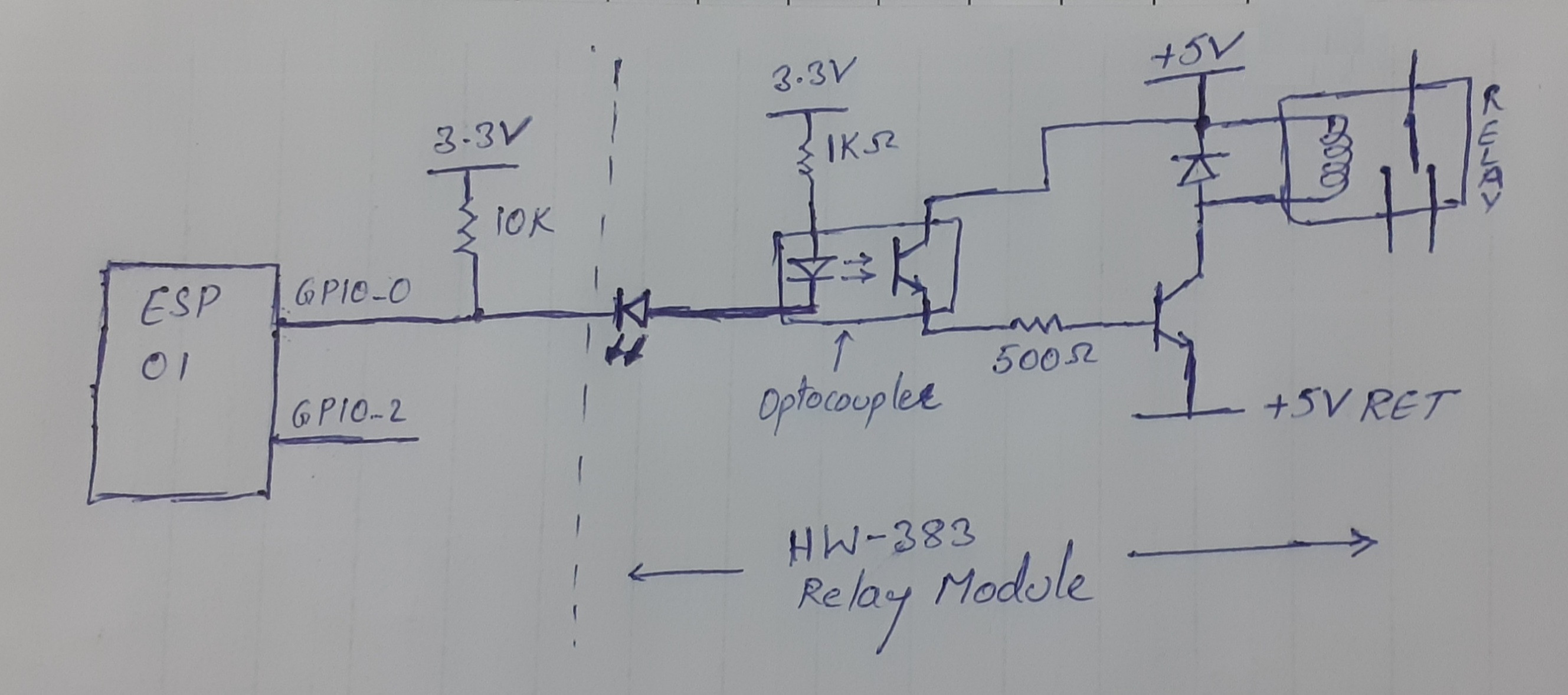
For this I bought an ESP-01 module and a 2-CH relay module (HW-383) and my schematic is as below (GPIO-2 has the same circuit as GPIO-0):

Schematic

The EPS-01 and the optocoupler share +3.3 V which is isolated from the +5 V used for relay and transistor. I pulled GPIO-0 and GPIO-2 to 3.3 V using 10 kΩ as it is necessary for ESP to boot properly.

Everything is working perfectly except the flicker (relay turn ON and then OFF) during ESP-01 boot or reset (in my code I have set GPIOs to HIGH and then set them as O/P).

I read that this is due to the internal process of the ESP module. A few people suggest using GPIO-2 to avoid flicker and a few suggest adding a 470 μF capacitor across the optocoupler input terminals (only few people had success with a capacitor).

Is it a good idea to add a capacitor across the optocoupler? Can I add a capacitor across the GPIO pin and 3.3 V_GND? Both ways cause the capacitor to discharge into the GPIO pins at LOW signal on GPIO, is this safe for the ESP-01? If so, what is the optimum value for the capacitor?

Or do I need to add an RC network between the GPIO and the optocoupler to delay the switch ON of optocoupler (schematic would be helpful)?

I know there are lots of discussions on this topic but I could not find a reliable solution.

Update:
Here's a link to detailed GPIO behavior during boot.

The last post in the form says "GPIO0 will output the clock frequency (e.g 26 MHz) of the external crystal by default".

I think this clock might be causing the relay to turn ON and OFF during boot. How to avoid relay turn ON during this clock output?

\$\endgroup\$
3
  • \$\begingroup\$ run the opto from gpio2 to gnd, nothing in series. works for me. \$\endgroup\$
    – dandavis
    Commented Dec 6, 2021 at 5:08
  • \$\begingroup\$ What about gpio2 pullup? I think gpoi0 and gpio2 needs to be pulled up for booting of esp. I am trying to use gpio0 and gpio2. \$\endgroup\$
    – kk345
    Commented Dec 7, 2021 at 2:28
  • \$\begingroup\$ "How to avoid relay turn ON during this clock output?" Just use a different pin. There is great reference on the safe pins to use here \$\endgroup\$
    – Maple
    Commented Apr 21, 2023 at 17:26

1 Answer 1

0
\$\begingroup\$

Don't add a cap between GPIO pins and ground, don't add caps between GPIO pins and 3.3v. You can draw too much current doing that and burn a pin.

GPIO 0 is needed for setting boot conditions (must be pulled high as your 10k resistor does.

Your problem comes from the two LEDs in series. Your optocoupler likely has an IR-LED with a 1.0 to 1.3v drop and your indicator LED is at least 2v drop (assuming red color). This means that driving GPIO 0 LOW to turn on the optocoupler will be very low current and any voltage line fluctuations (like the load on your relay or even the ESP checking wifi) my cause brownout conditions.

First, Try removing your indicator LED. If that fixes your problem, you can move the indicator to a position parallel to the 10k pull-up resistor (add a current-limiting series resistor to the Indicator LED).

\$\endgroup\$
7
  • \$\begingroup\$ If you cannot move the indicator LED, can you change the 3.3v supply for the Optocoupler LED to 5v instead of 3.3v? That would overcome the high forward voltage of the two LEDs in series. The Vf of the LEDs will insure the GPIO 0 input will not see the full 5v. \$\endgroup\$ Commented Dec 5, 2021 at 13:56
  • \$\begingroup\$ Note on this link from the manufacturer of the relay module, the raspberry pi example uses an orange wire from the raspberry pi to the breadboard red power rail. Although the raspberry pi is a 3.3v device, the orange pin is connected to a +5v power pin that is directly connected to the .USB power input (5v) as the relay board's power source. Here is the link. The raspberry pi example is at the bottom of the page. wiki.sunfounder.cc/index.php?title=2_Channel_5V_Relay_Module \$\endgroup\$ Commented Dec 5, 2021 at 14:14
  • \$\begingroup\$ I have checked the circuit by powering the optocoupler using 5V but still no use. During ESP boot or reset the relays are getting ON and OFF. I have updated my question with a link. It says "GPIO0 will output the clock frequency (e.g 26MHz) of the external crystal by default". This might be causing relay ON/OFF during boot. How to avoid relay ON during clock O/P on GPIO. \$\endgroup\$
    – kk345
    Commented Dec 5, 2021 at 16:14
  • \$\begingroup\$ On boot, all of the GPIO pins on ESP8266 become high-impedance inputs so no current will flow through your Optocoupler (in the inout state, no current flows). The ESP8266 will not start unless that pin is an input with a pull-up resistor (your 10k). Current will only flow through the optocoupler after you assign it as an output in code (and set LOW). \$\endgroup\$ Commented Dec 5, 2021 at 18:23
  • \$\begingroup\$ If you want the relay to always stay on and use the ESP8266 to turn it off on some occasions, you can wire the hardware differently. Give me a few minutes for that option... \$\endgroup\$ Commented Dec 5, 2021 at 18:24

Your Answer

By clicking “Post Your Answer”, you agree to our terms of service and acknowledge you have read our privacy policy.

Not the answer you're looking for? Browse other questions tagged or ask your own question.