I have conducted a test where I already found out the temperature rise of the pcb traces in question. The product has a relay output accessible by the user on an output terminal block. The relay contacts are routed from the actual PCB pad (where the through hole relay is soldered) to the terminal block via PCB trace or leadwires. The test I conducted was done at starting temperature of ~27°C (room temperature).

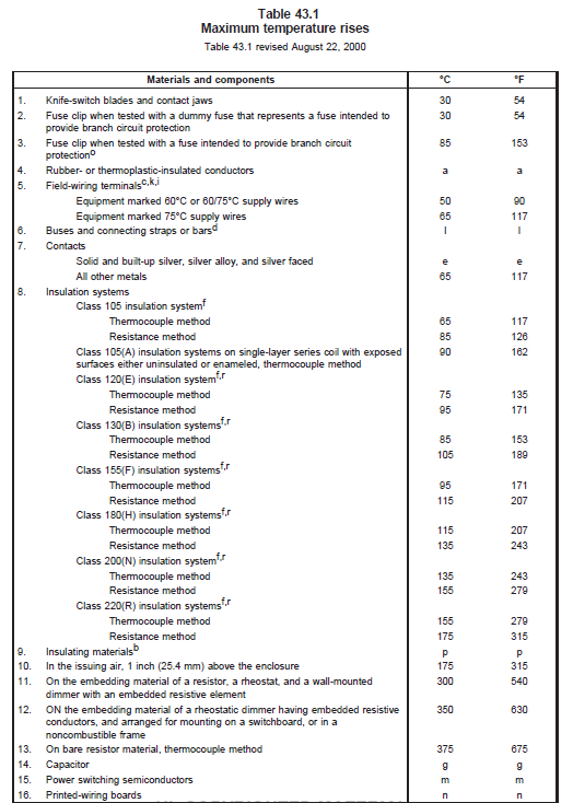
The problem I have is deciding the allowable temperature rise for PCB traces. From UL 508, there is table 43.1 that states the max temperature rises of different components/materials. However, it says that table 43.1 is for devices with max operating temp of 40 °C.

Our product's stated operating temperature range is -10 to 50 °C for reference. 1st question: Is the rated temperature of our product that maximum value on its operating range (50 °C)?
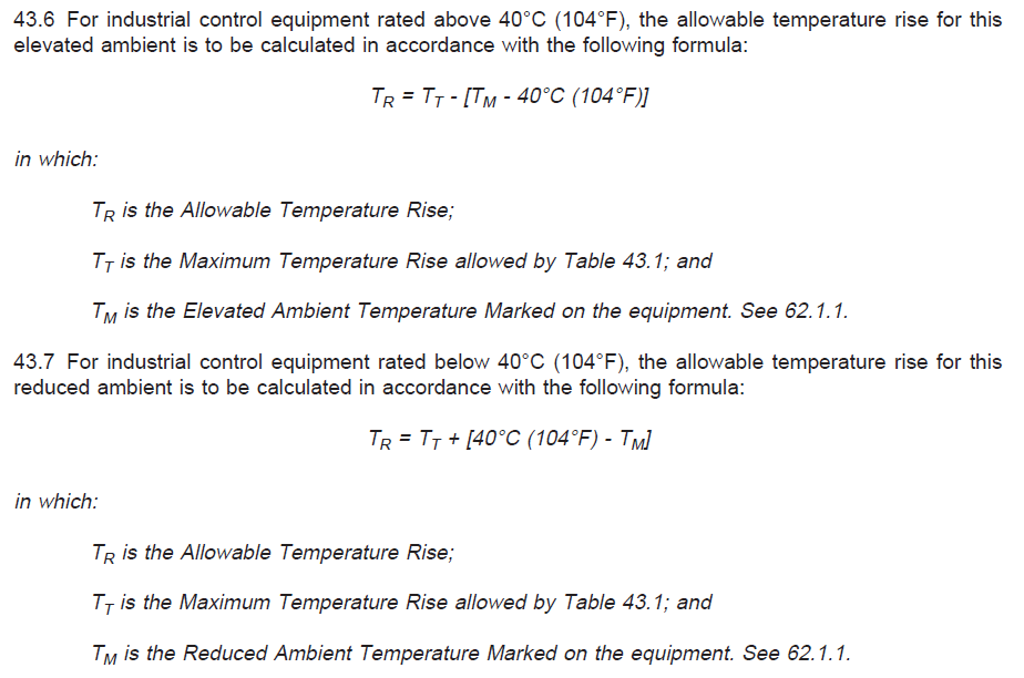
Going back to the UL file, there is a section saying:

So using rated temperature of our product as 50 °C (assuming this is correct, see 1st question above), then I would use the formula in 43.6. I get the following:
Tr=Tt-(Tm-40)
Using table 43.1 and the row for printed wiring boards, I go to comment 'n'.
2nd question: What is the operating temperature of the board? Is it based on material (FR-4) or based on the rated temperature of the product as a whole (50 °C)? Using 50°C, I get Tt = 50-40 = 10°C.
Now I only need Tm (Elevated ambient temperature marked on equipment). The pdf file points to 62.1.1.
It appears that Tm = 50 °C in my case? (max operating temp. of product) So finally, the formula becomes: Tr=Tt-(Tm-40)
Tr=10-(50-40) = 0, telling me my allowable temperature rise is 0°C. I believe I messed up somewhere on calculation (or maybe wrong interpretation of variables). Can anyone help me out?


