0
\$\begingroup\$

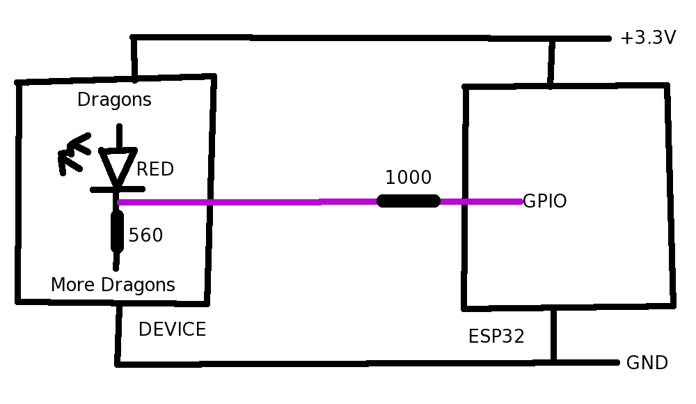
crude drawing

I am trying to interface the status LEDs of a third-party device to the GPIO of my ESP32. I am using internal pull-ups on the ESP32 inputs and trying to trigger on the voltage drop that occurs when the LEDs switch on.

For blue and green LEDs, this voltage drop is from +3.3 V to +0.8 - 1.0 V, and the ESP32 triggers fine. The voltage drop of the red LED is much smaller, from +3.3 V to +2.16 V, which is insufficient for my ESP32.

Within the device, both anode and cathode of the LEDs disappear into active circuitry that I don't control, and I mustn't load this device too much.

I know I might be able to solve this problem by programming my ESP32 differently, but my preferred solution would be to pull +2.16 V closer to 0 V, to get a nice logic level. I don't need bidirectionality, and inverting the logic would be OK if this is a major simplifier. There is no particular bandwidth requirement, although the LEDs happen to be PWM-driven at 4kHz.

\$\endgroup\$
5
  • \$\begingroup\$ A pretty simple solution would be to use a comparator with a setpoint somewhere between 3.3 V and 2.16 V. \$\endgroup\$
    – Klas-Kenny
    Commented Dec 6, 2021 at 10:12
  • \$\begingroup\$ Can you read the voltage with ADC input? \$\endgroup\$
    – Justme
    Commented Dec 6, 2021 at 10:30
  • \$\begingroup\$ Justme, I think I then wouldn't be able to set an interrupt on this pin, and other complications, etc. Hoping to fix it with wires instead of code! \$\endgroup\$
    – donotpanic
    Commented Dec 6, 2021 at 11:00
  • \$\begingroup\$ Klas-Kenny, could you suggest a part? SMT is OK, though hand-workable packages are preferred. \$\endgroup\$
    – donotpanic
    Commented Dec 6, 2021 at 11:02
  • \$\begingroup\$ SMT is perfectly "hand workable." \$\endgroup\$
    – JRE
    Commented Feb 3, 2023 at 11:07

2 Answers 2

2
\$\begingroup\$

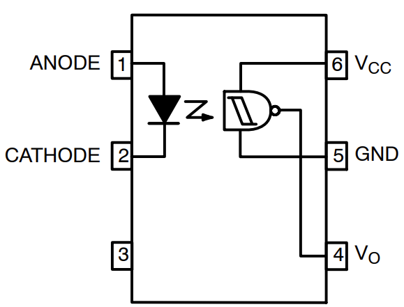
Given the vagueness of the rest of the circuit, I would strongly recommend you use a high sensitivity, logic-level opto-coupler such as an H11L1.

enter image description here

(Logic symbol taken from the onsemi datasheet for the H11L1)

On the input side, you are effectively putting another LED and a resistor in parallel with the existing LED and resistor. If you select a high sensitivity coupler, you only need to draw ~1mA, which is probably a fraction of what the existing LED is drawing, and is almost certainly covered by the design margin of the existing setup.

On the receiver side you get a direct logic level output referenced to your ESP32 rails.

Job done.

(Optocouplers are a much overlooked technology, but are used widely in everything from high-side FET drives, to galvanic isolation of comms lines. "Go optocouplers!")

\$\endgroup\$
1
  • \$\begingroup\$ There are multichannel versions available if you need to monitor multiple LEDs, saving on package count and supply wiring. \$\endgroup\$
    – colintd
    Commented Feb 3, 2023 at 14:57
0
\$\begingroup\$

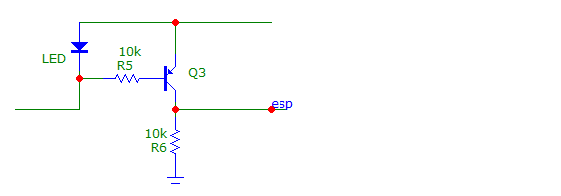
If the anode of the red LED is connected to +3V3, then you can use something like that. The transistor will turn on if there is more than about 0.6V on the LED, and that will pull the ESP input high.

enter image description here

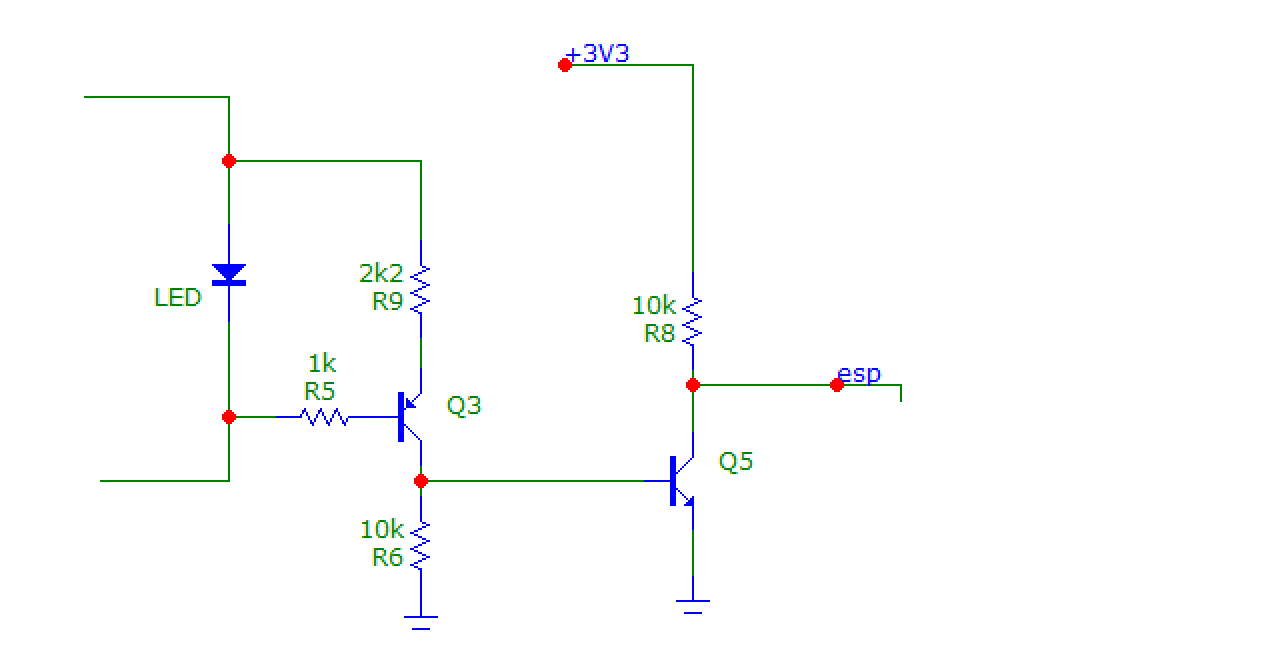
If the anode isn't connected to +3V3, for example if the LEDs are multiplexed, then...

enter image description here

When the LED turns on, there will be ~1.8V across it, so Q3 acts as a current source of about 1.8V-Vbe = 540 µA. That turns on Q5, and the ESP input is pulled low.

\$\endgroup\$
3
  • \$\begingroup\$ Hi Bobflux, you're correct that the LEDs are multiplexed. It's also fairly difficult (but not impossible) for me to reach their common anodes. That common anode does indeed not connect directly to VCC, as noted. \$\endgroup\$
    – donotpanic
    Commented Dec 6, 2021 at 10:59
  • \$\begingroup\$ OK so second circuit then. If the LEDs are multiplexed, and you only sense voltage on cathode, that will only tell you when one LED is on out of the bunch of LEDs that share the same cathode wire, but it won't tell you which one is on. So you have to sense voltage across the LED, not just one one pin. \$\endgroup\$
    – bobflux
    Commented Dec 6, 2021 at 11:02
  • \$\begingroup\$ I currently get acceptable results for Blue and Green LEDs between 3.3 VCC and their respective cathodes. I don't know exactly what goes on in the device, but when the device is unpowered a megohm resistance is measured (in both directions) between their anodes and VCC. Megohms between cathode and ground, also. (Dragons, maybe.) It'd be nice if I could continue to avoid tapping that multiplexed anode directly. \$\endgroup\$
    – donotpanic
    Commented Dec 6, 2021 at 11:11

Your Answer

By clicking “Post Your Answer”, you agree to our terms of service and acknowledge you have read our privacy policy.

Not the answer you're looking for? Browse other questions tagged or ask your own question.