0
\$\begingroup\$

I'm currently studying the textbook Fundamentals of Electric Circuits, 7th edition, by Charles Alexander and Matthew Sadiku. Chapter 2.4 Kirchhoff's Laws gives the following example:

Kirchhoff’s current law (KCL) states that the algebraic sum of currents entering a node (or a closed boundary) is zero.

...

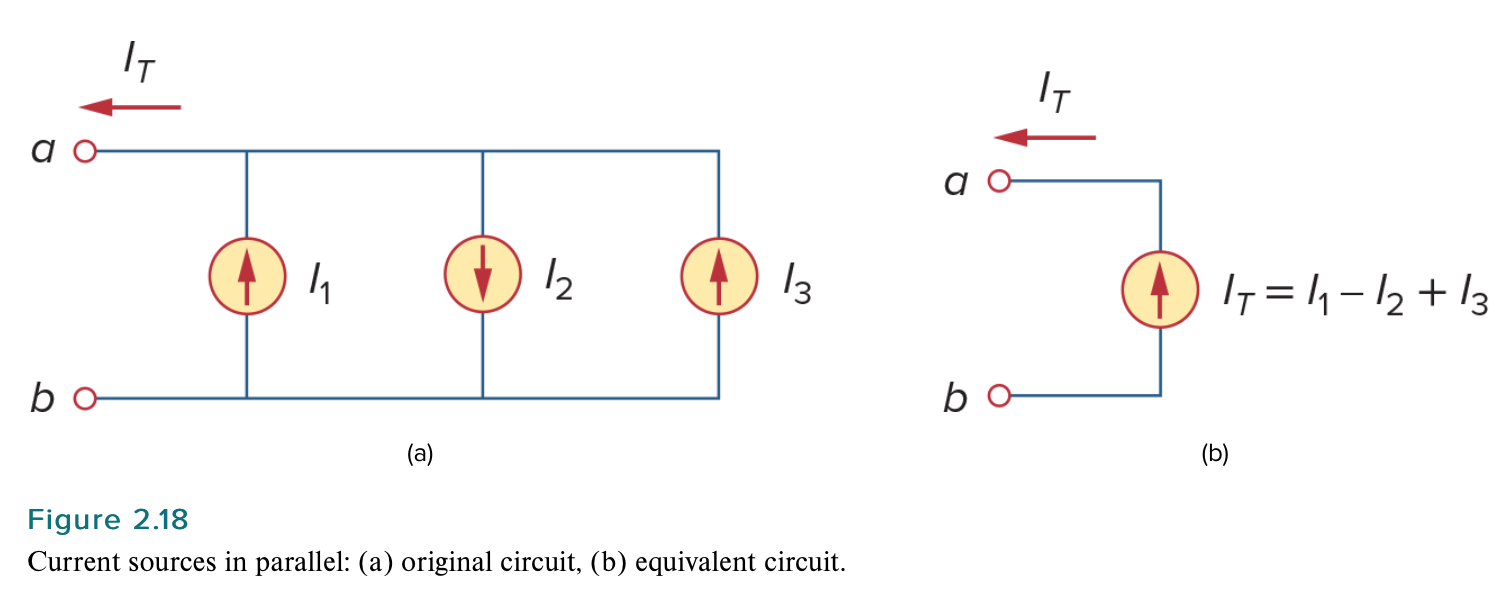
A simple application of KCL is combining current sources in parallel. The combined current is the algebraic sum of the current supplied by the individual sources. For example, the current sources shown in Fig. 2.18(a) can be combined as in Fig. 2.18(b). The combined or equivalent current source can be found by applying KCL to node \$a\$. $$I_T = I_1 - I_2 + I_3$$ enter image description here A circuit cannot contain two different currents, \$I_1\$ and \$I_2\$, in series, unless \$I_1 = I_2\$; otherwise KCL will be violated.

I don't understand why a circuit cannot contain two different currents in series, and why this would violate Kirchhoff's current law. If two currents, such as \$I_1\$ and \$I_2\$, are in series, then wouldn't the current just be the net of the two, as shown in 2.18(b)? I get the impression that I am misunderstanding/misinterpreting what this is saying.


EDIT

For some reason, despite the fact that we've had four answers, no one has yet explained this concept. The closest we've come is Neil_UK, who just commented that my reasoning is incorrect since I am assuming that the currents also add in series, just as they do in parallel. So why exactly is it incorrect to assume that the currents add in series, just as they do in parallel? This seems like it would be the natural assumption. What is the correct way to think about this?


EDIT2

From the same textbook, “a branch represents a single element such as a voltage source or a resistor.” And, again, from the same textbook, “a node is the point of connection between two or more branches.”

\$\endgroup\$
6
  • 1
    \$\begingroup\$ Basically what you ask is in the quote already : "The combined current is the algebraic sum of the current supplied by the individual sources." \$\endgroup\$
    – Justme
    Commented Dec 6, 2021 at 10:33
  • 1
    \$\begingroup\$ Current "in series" means that there is a single path where the output of I1 feeds directly into the input of I2. What is shown in figure 2.18 is current "in parallel", which is different because source I1 and source I2 can have different currents. \$\endgroup\$
    – MarkU
    Commented Dec 6, 2021 at 10:48
  • \$\begingroup\$ Do you understand what an ideal constant current source is? \$\endgroup\$
    – G36
    Commented Dec 6, 2021 at 14:50
  • 1
    \$\begingroup\$ Down voted because this has been clearly explained over and over. \$\endgroup\$
    – Ed V
    Commented Dec 6, 2021 at 17:53
  • 2
    \$\begingroup\$ @EdV so you can easily find the question this is a duplicate of, right? \$\endgroup\$ Commented Dec 6, 2021 at 18:11

9 Answers 9

12
\$\begingroup\$

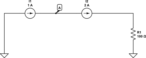
Here is the circuit we understand you to mean when you say "two currents in series":

schematic

simulate this circuit – Schematic created using CircuitLab

For I2 to be a 2 A current source, 2A must be flowing in to its left terminal and 2 A flowing out of its right terminal. But for I1 to be a 1 A current source, 1 A must be flowing in to its left terminal and 1 A flowing out of its right terminal.

That means 1 A is flowing in to node A from the left but 2 A is flowing out of node A to the right. And no other branches connect to node A.

What your book means by saying "KCL will be violated" is if you form a KCL equation at node "A", you get

$$1\ {\rm A} = 2\ {\rm A}$$

which is a logical contradiction.


To address the edits in your question post,

From the same textbook, “a branch represents a single element such as a voltage source or a resistor.” And, again, from the same textbook, “a node is the point of connection between two or more branches.”
Yes, but two branches are in series only if there is no other branch that also connects at their common node. For example I1 and I2 are two branches in my diagram above that connect at node A. No other branch connects to node A and therefore I1 and I2 are in series.

So why exactly is it incorrect to assume that the currents add in series, just as they do in parallel?

It's a matter of the sign convention for the branches.

A generic way to write KCL is

$$\sum_n I_n = \sum_m I_m,$$

where each \$I_n\$ is the current of a branch with its reference direction pointing in to the node, and each \$I_m\$ is the current of a branch with its reference direction pointing out of the node.

When we talk about branches in parallel we typically have one source branch on the left side of this equation and two or more load branches (the parallel branches) on the right side of the equation. Since all the load branches are on the right side, their currents add.

When we talk about branches in series we have exactly two branches connecting at a node, and we put one branch on the left side (we take its reference direction as pointing in to the node) and one on the right side (we take its reference direction as pointing out of the node). In this case we get that the two currents must be equal.

\$\endgroup\$
8
\$\begingroup\$

Consider two pumps connected with one sending 5 gallons per minute to the other that passes 2 gallons per minute. How can that happen?

\$\endgroup\$
0
7
\$\begingroup\$

As you say you need to be spoon-fed, I need to make a number of observations.

  • 'Ideal' components are abstractions, simplified models of the real world, that are sometimes not too intuitive.

  • Ideal current sources are even less intuitive (for most people) than ideal anything else.

  • Starting with a text book talking about how these ideal sources combine may not be the best first steps to take.

Would analogies help? An electrical current is the rate of flow of charge. Charge can't be created or destroyed, but can be moved from place to place. Marbles can't be created or destroyed (in our simplified world) so could stand in for charge. A marble current would therefore be m marbles per second being moved from some input to some output.

Imagine we have a constant marble current source, that takes one marble per second from an input hopper, and delivers it to an output hopper (youtube has almost as many marble-machine videos as cat videos, so find a few to get your intuition going if needed). Let's have another marble current source that delivers 2 marbles per second between a corresponding pair of hoppers.

If we put those in parallel, side by side, then the input hoppers will lose 3 marbles per second, and the output hopper gain three per second. This is the same behaviour as a pair of electrical current sources in parallel.

Now let's put them in series. Consider the in/out hopper between the two sources. If the 2 marble source is first, and is feeding the 1 marble machine, then the intermediate hopper will start to fill. This is what happens in real life electricity too. Marbles, or charge, builds up at an intermediate node, until something breaks. In the marble world, the hopper level becomes too high for the marble source to lift them to, or the hopper becomes too heavy and collapses. In the electrical world, charge builds up and the voltage (corresponding to the marble level in the hopper) at the intermediate node increases.

If the voltage becomes too high for the input current source to supply, it stops being an ideal source and stops supplying current. In the real world, we say its 'output compliance voltage' has been exceeded. But this is messy, as it depends on the details of the physical thing that's supplying the current. So we simplify. In the ideal world, where its output compliance voltage would be infinite, we say it 'can't happen'. Or rather, we say that simplified model no longer applies.

In the real electrical world, that hopper would be referred to as stray capacitance to ground from that node. Having it there allows any current imbalance to be accumulated for some time. In the ideal world, we can model that capacitance, and watch as our intermediate node voltage rockets off at a prodigious rate, for instance a 1 A imbalance between two series connected current sources and an assumed 10 pF stray capacitance means the voltage would increase at 100 kV per microsecond.

The only way this quick change of voltage doesn't happen is for there to be no imbalance current. For most circuits we observe, intermediate nodes don't rocket off to infinity.

\$\endgroup\$
4
\$\begingroup\$

Go back to the fundamentals of what a current is. 1 ampere is 1 coulomb passing a point per second. 1 coulomb is approximately 6.24x10¹⁸ electrons.

So if 1 amp is flowing through a component, or a wire, then 6.24x10¹⁸ electrons are going through it every second. If two components are in series, then you can't have different number of electrons flowing through each of them. Either electrons would be piling up somewhere, or they would have to be created out of nothing.

That's fundamentally what Kirchhoff's current law is saying - the number of electrons going into any point in a second must equal the number of electrons going out again.

So not only do two different currents in series not add up, it's not even possible.

\$\endgroup\$
3
\$\begingroup\$

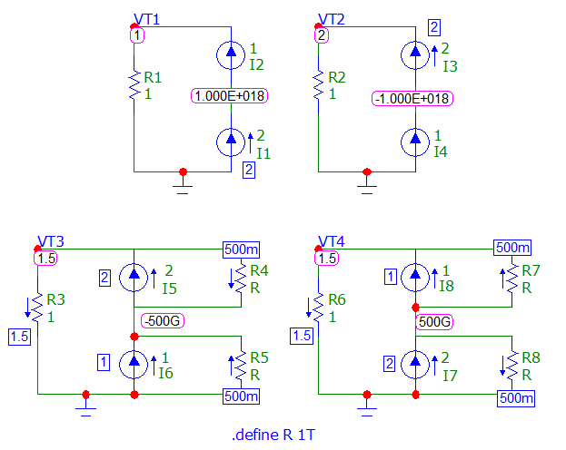
EDIT2: I have added a new picture for DC Analysis (added resistor with source current).

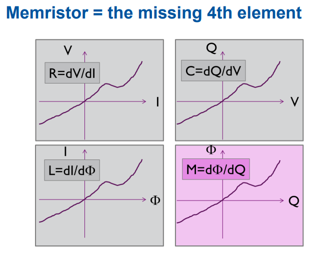
EDIT: KCL and KVL are not a "concept". They are only a "fact" that can be verified and that does not give "contradictory" results (the pictures below), as long as you applied it (example: EET and so on). The only way to prove this, "ad contrario", is to "create and try" such a "device" (as for example folio 20 "memristor" -- what is this "weird" device --, and so on ...) and discover that more general law is also verified for these devices. There is also "memistor" which are different.

Memristors from subdirectory MemElements from microcap v12

enter image description here

From this.

KCL is "conservation of charge" (Or current) ...

Must be true also in a ... branch if you cut between the two current sources.

Be careful with a simulator that doesn't give an "error" ... when one wire these current source in serial.

Here is a Dynamic DC analysis and a transient analysis. Would be interesting to know if others share the same behaviors.

So, the fact that the simulators do not give the same answer when one swaps the current sources is also the fact that laws are certainly violated. This is because real source current must have a parallel resistor when they are used "alone", otherwise the voltage at the terminals would be infinite ... which is obviously an aberration.

You can see this in the DC analysis where voltage is: + or - 1000 TV! Remember also that some simulators add a resistor to the ground of 1TOhm (can be changed).

enter image description here

enter image description here

\$\endgroup\$
6
  • \$\begingroup\$ I’m not sure that this answers my question. \$\endgroup\$ Commented Dec 6, 2021 at 11:14
  • \$\begingroup\$ Ok, I understand that Kirchhoff’s current law would be violated, but there’s no explanation here for how, or what exactly I’m misunderstanding. \$\endgroup\$ Commented Dec 6, 2021 at 11:23
  • \$\begingroup\$ A current generator is a perfect "device" that forces its only current into a branch of a circuit. How can we use another current source to force another current in the same branch? \$\endgroup\$
    – Antonio51
    Commented Dec 6, 2021 at 11:27
  • \$\begingroup\$ Well, on could imagine that the one with greater current overpowers the one with lower current, and so this is where my idea regarding the net of the currents comes from. \$\endgroup\$ Commented Dec 6, 2021 at 11:29
  • \$\begingroup\$ Yes. It could. It is, de facto, the same "problem" as with 2 voltage generators in parallel. Must see what are "really" the "initials conditions" (validity of laws) of writing these equations. I would just show also that simulators are not "perfect". \$\endgroup\$
    – Antonio51
    Commented Dec 6, 2021 at 11:49
2
\$\begingroup\$

If two currents, such as I1 and I2, are in series, then wouldn't the current just be the net of the two

If the "combined" current is \$I_1+I_2\$ then that current must flow through the current source producing \$I_1\$ and that is a violation because \$I_1+I_2\$ cannot equal either \$I_1\$ (or \$I_2\$).

It's the same for paralleled ideal voltage sources. If both have the same voltage output then no problem; the two can be merged into one single ideal voltage source. However, if the two have different voltage values then an infinite current circulates and that prevents sensible thinking and analysis.

\$\endgroup\$
5
  • \$\begingroup\$ I really don’t understand why this would imply that an infinite current circulates. \$\endgroup\$ Commented Dec 6, 2021 at 11:19
  • \$\begingroup\$ If you put a 12 volt battery in parallel with a 6 volt battery, think what would happen. What would be the resulting terminal voltage of both batteries connected in parallel? How much current will be drawn from the 12 volt battery when it's terminal voltage is dragged down towards 6 volts? \$\endgroup\$
    – Andy aka
    Commented Dec 6, 2021 at 11:26
  • \$\begingroup\$ I’m on chapter 2 of an introductory electric circuits textbook, so exactly what level of intuition do you expect me to have to be able to answer such a question and understand the point you’re making? This is just complicating matters, when what someone at my level needs is straight-forward, spoon-fed explanations. \$\endgroup\$ Commented Dec 6, 2021 at 11:33
  • 1
    \$\begingroup\$ I have no idea at what level you are. To be able to know that I would have to be a mind reader. So, instead, I asked you a pertinent question that might reveal your skill level to me. I have no idea what textbook either and, even if I did, I won't have that text book. I didn't know that you need spoon-fed explanations. How could I know that? \$\endgroup\$
    – Andy aka
    Commented Dec 6, 2021 at 11:35
  • \$\begingroup\$ Anyway, stick to the current source stuff; if a current source is producing 1 amp then it can't be forced to produce anything other than 1 amp without odd things happening. It's the nature of the beast. \$\endgroup\$
    – Andy aka
    Commented Dec 6, 2021 at 11:38
1
\$\begingroup\$

enter image description here

Your 2 circuits above are equivalent when seen from terminals a and b - no problem there, the rightmost circuit works exactly as well as the leftmost one.

Unfortunately your rightmost circuit presents a current source which pushes current through nothing conductive. That's not generally allowed, there should be something connected to the terminals - except in one case. If the sum of the currents (=It) happens to be zero, there's drawn no impossibilities and everything would be OK.

\$\endgroup\$
3
  • \$\begingroup\$ Ok, but how does this explain why a circuit cannot contain two different currents in series, and why this would violate Kirchhoff's current law? \$\endgroup\$ Commented Dec 6, 2021 at 11:54
  • \$\begingroup\$ The question which was only text is already answered by others like this: "Just the joint of 2 current sources in series is a node which has 2 wires. The sum of the currents to that joint must be zero." Kirchoff took his law from the experimental observation that no charge can vanish nor be born from nothing. It was not proven from anything more fundamental, it was only believed because all observations seemed to support it. \$\endgroup\$
    – user136077
    Commented Dec 6, 2021 at 12:05
  • \$\begingroup\$ (continued) Even today no exceptions are found. Charged particles can vanish or be created in cosmic particle reactions, but the process removes or creates as much plus- and minus charge. Kirchoff published his laws in 1845. It took several decades before some more fundamental laws behind the observed physical conservation laws were found. If you want some headache start for ex. from this en.wikipedia.org/wiki/Noether%27s_theorem . It was originally written in 1915. \$\endgroup\$
    – user136077
    Commented Dec 6, 2021 at 18:51
0
\$\begingroup\$

Voltage source in series with a resistor is equivalent to a current source in parallel with that resistor.

So current source is nothing but just a current flowing in a circuit with a resistor in parallel, the resistor which was in series with the voltage source.

The magnitude of the current or current source is determined by voltage source divided by the resistance of the resistor and that is the current in all the circuit. So you can not put two different current sources in a same loop because only a specific magnitude of the current flows in the circuit in series connected components. But yes you can show the current source in series if they have same magnitude because same current is flowing in the loop.

\$\endgroup\$
1
  • \$\begingroup\$ While Norton-Thevenin equivalence is valid, it has nothing to do with this question. \$\endgroup\$
    – Ben Voigt
    Commented Dec 6, 2021 at 18:21
0
\$\begingroup\$

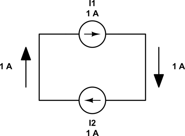
Take the following schematic:

schematic

simulate this circuit – Schematic created using CircuitLab

You see, in every wire (black lines) there is exactly 1 A flowing, and both the current generators (I1 and I2) are happy because they both see 1 A entering and 1 A exiting.

Just now, we see that the current flowing is 1 A, not 2!

But suppose that we set current generator I2 to 2 A. I2 will do its best to make 2 A flow. Being an ideal current generator, it will collapse the entire universe, if needed, to get the necessary energy to make 2 A flow. The problem is that current generator I1 does the same: being ideal, it will consume the universe to insist that the current flowing "MUST BE 1 ampere!".

If we think that ideal current generators do not exist, the real current flowing, in a real situation, will be something in between the two "nominal currents" of the generators but, again, not their sum. Being not ideal, real current generators must leave something to their enemies: for example, for generators of 1A and 2A, the real current could be 1.5A, with each generator giving away something (0.5A) to the enemy.

Probably the concept to stress is that a current generator tries to regulate the current, be it "by pushing it" or "by pulling / braking it", just like a voltage generator tries to regulate voltage. Often we think a voltage generator sources current to keep the voltage, but it can also sink current if we try to raise the voltage.

\$\endgroup\$

Your Answer

By clicking “Post Your Answer”, you agree to our terms of service and acknowledge you have read our privacy policy.

Not the answer you're looking for? Browse other questions tagged or ask your own question.