0
\$\begingroup\$

I am working on an audio project using the THAT1646 balanced output driver (project is a hi-fi mixer for studio insert gear). The project uses a bipolar +/-15V supply.

I am experiencing distortion on the device output which I tracked down to the THAT1646 at the output, using a scope and a sine wave from a test signal generator.

At the input of the THAT1646 I see my clean test waveform, but with a large DC bias, appearing to center around the negative rail. At the output of the THAT1646 I see a distorted version of my waveform, also centered around the negative rail. Any idea what might be causing this?

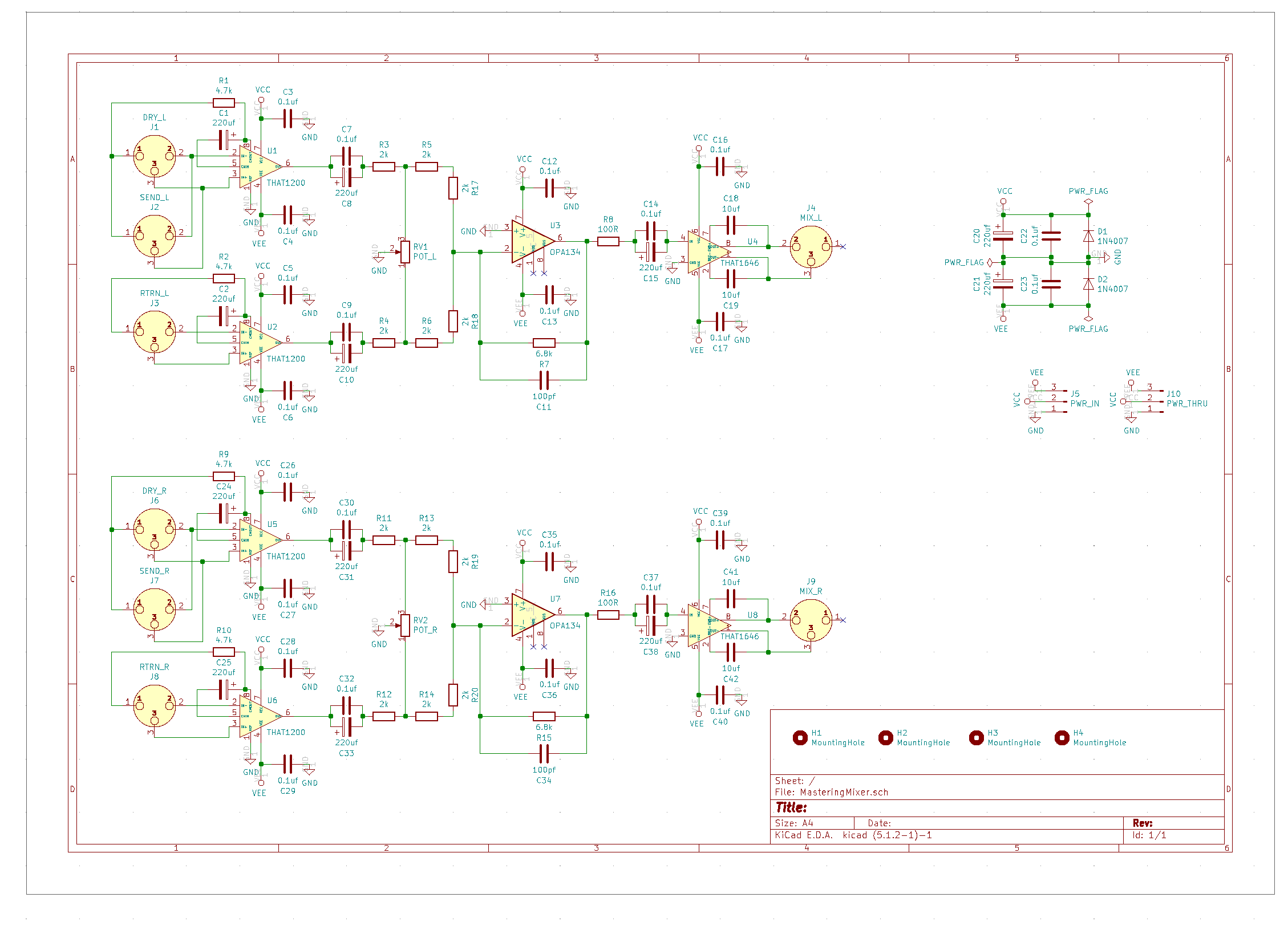
I am using the Fig.5 example circuit from page 7 of the THAT1646 datasheet:

enter image description here

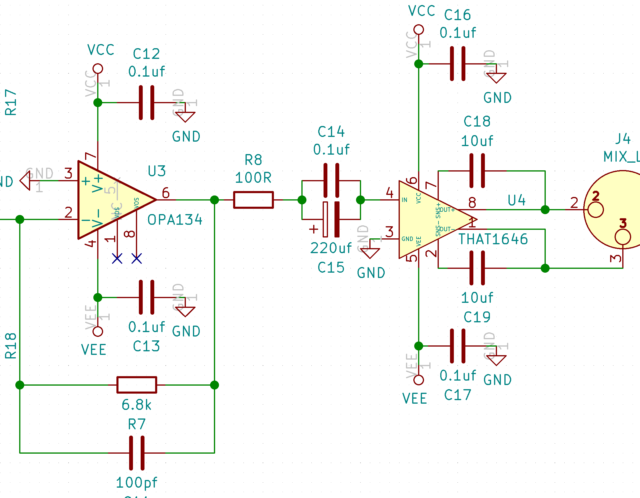
Here is a picture of the relevant schematic section, I see a clean sine wave centered at 0V until after the C15 coupling cap:

enter image description here

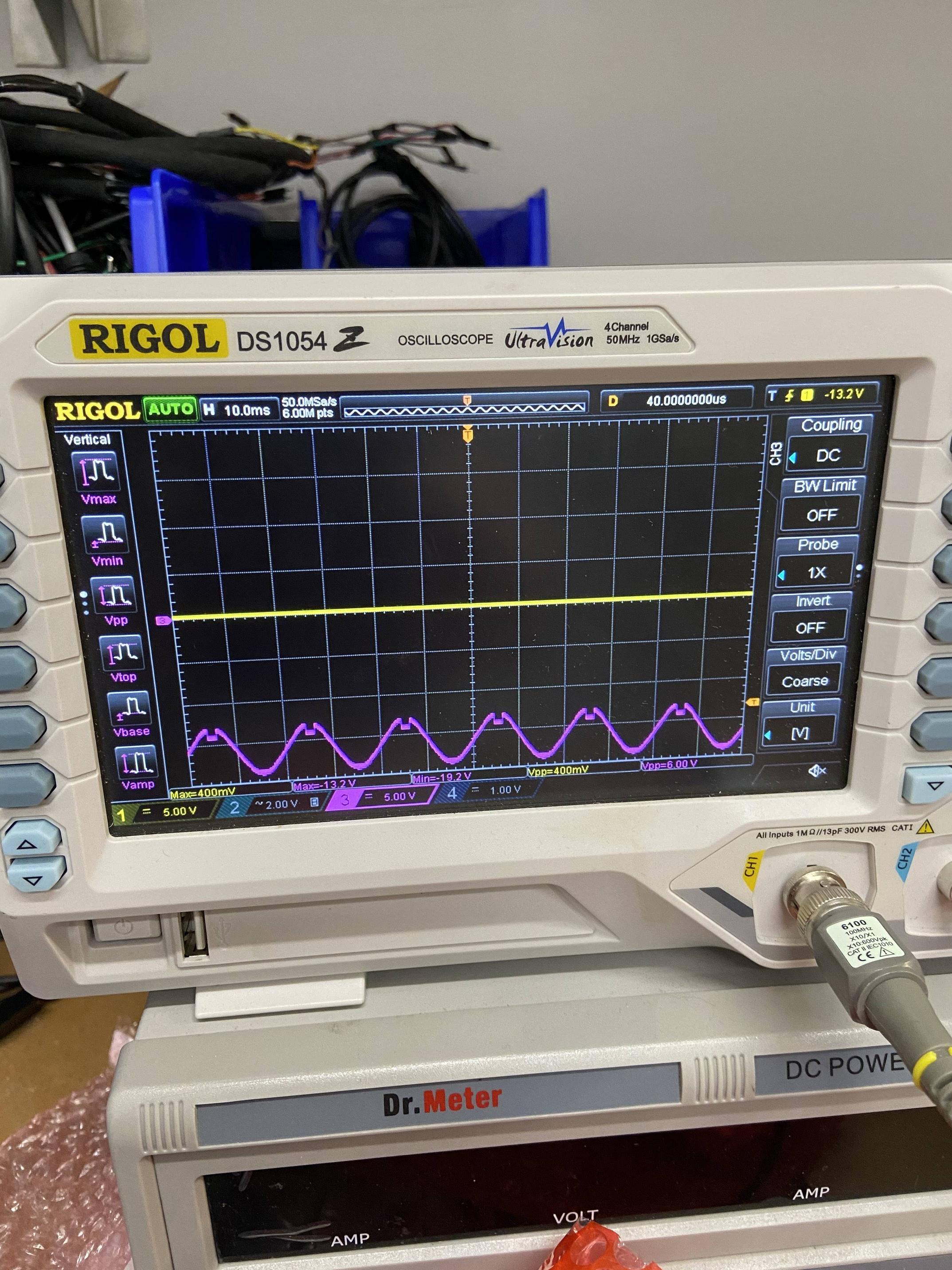
Here is the distorted output at THAT1646 pin 8:

enter image description here

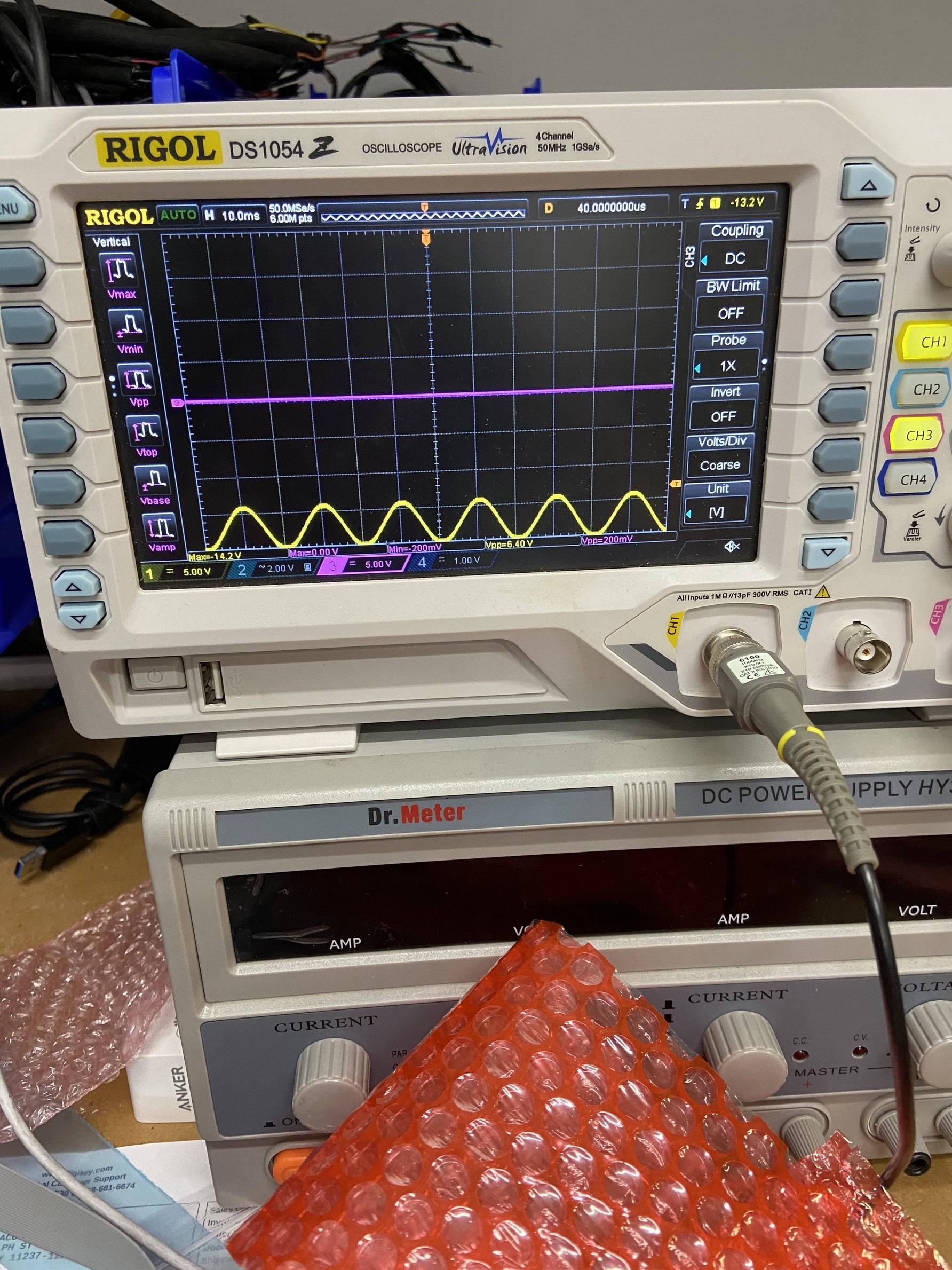
Here is the input at pin 4 of THAT1646, showing a heavy DC bias:

enter image description here

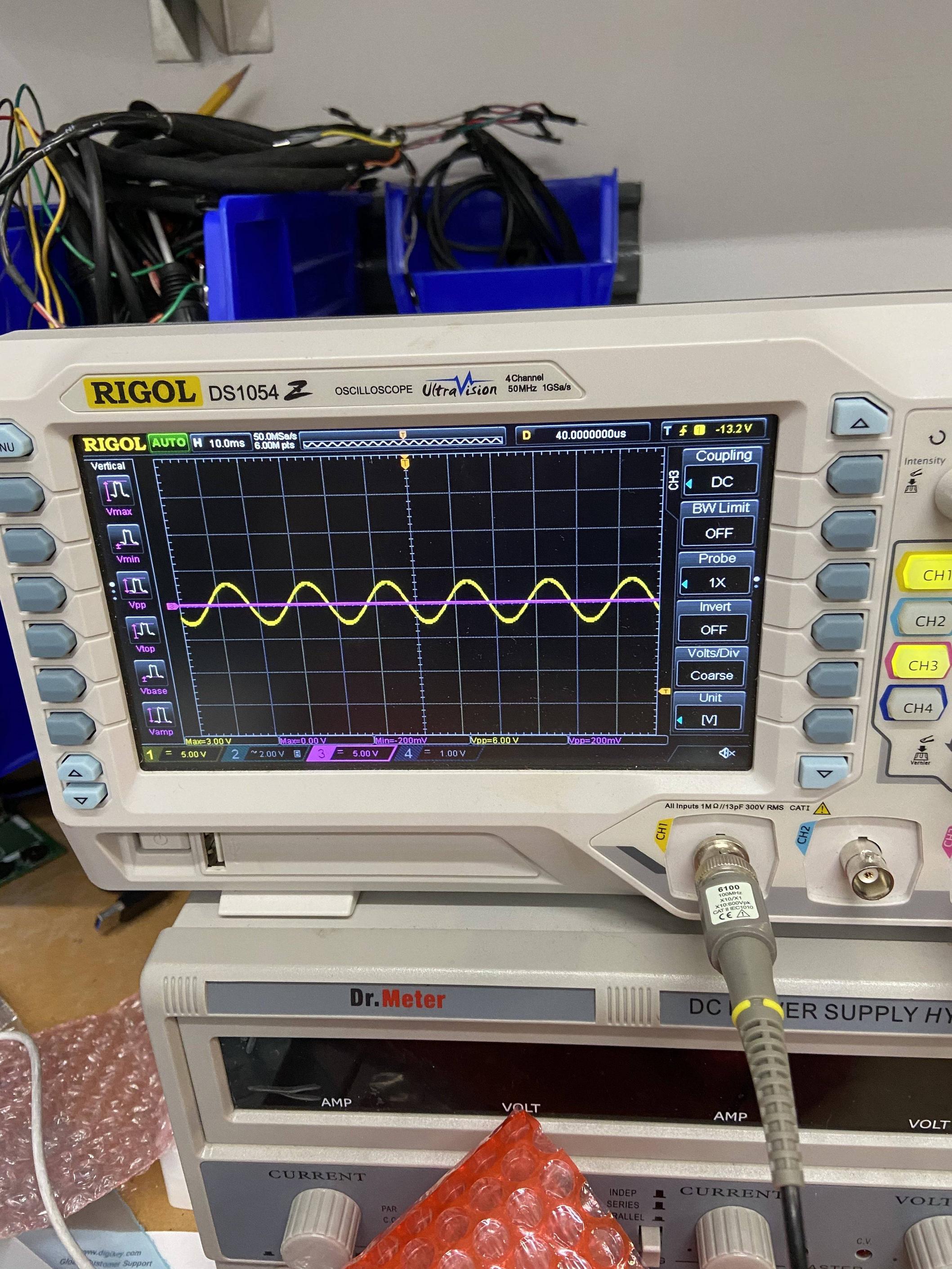
Here is the clean sine wave, centered at 0V, that I see before C15:

enter image description here

Here is the circuit as a whole. Please note that ground pins of xlr jacks have been left floating on the board as they are grounded via the device chassis (I have taken care to simulate this in testing):

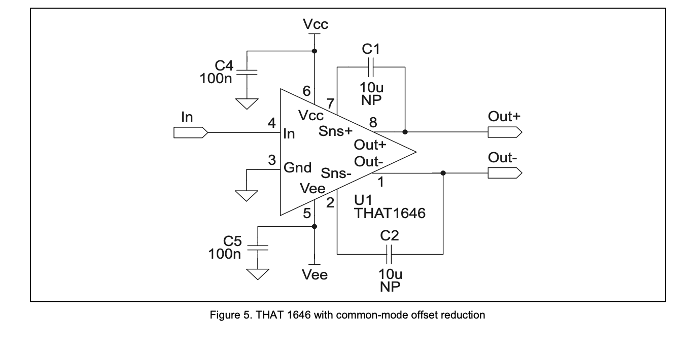
enter image description here

\$\endgroup\$
5
  • \$\begingroup\$ Maybe the IC is defective. \$\endgroup\$
    – Audioguru
    Commented Dec 10, 2021 at 23:10
  • \$\begingroup\$ I'd like to understand why the balanced driver input is AC coupled, what indication there is it works without a DC path? That may be the only problem. \$\endgroup\$
    – Justme
    Commented Dec 10, 2021 at 23:12
  • \$\begingroup\$ Try removing (shorting) C14,C15 - they shouldn't be necessary anyway, as the input is already centered around ground. \$\endgroup\$
    – td127
    Commented Dec 11, 2021 at 1:49
  • \$\begingroup\$ @td127 that makes sense, I will try that when I'm back at the bench \$\endgroup\$ Commented Dec 11, 2021 at 18:19
  • \$\begingroup\$ I agree with @Justme that the underlying problem is likely lack of a DC path for the bias current from pin 4 (although it's not clear from the datasheet, at least to me). \$\endgroup\$
    – td127
    Commented Dec 11, 2021 at 18:22

2 Answers 2

1
\$\begingroup\$

Could be a number of things:

Could be common mode range issues or clipping, try DC biasing the + pin to a different value (maybe with a potentiometer) because the pin is essentially floating.

The output will only go to within Vcc-2.2V and Vee+2.5 so if the gain is to high you might be clipping (and amplifiers do weird things when they clip)

\$\endgroup\$
0
\$\begingroup\$

If there is no DC path to ground from the input of the opamp, then tiny input bias current will eventually charge the coupling caps to a DC voltage that clips the opamp.

You need to either remove the coupling caps and DC-couple it, or add a high value resistor like 100k from the input to ground to provide a path for the bias current.

\$\endgroup\$
2
  • \$\begingroup\$ Hi, sorry for the delay in reply, I have been out of office for Christmas. \$\endgroup\$ Commented Dec 25, 2021 at 23:31
  • \$\begingroup\$ I tried adding a 10k resistor to group after the DC blocking cap, and I still saw it sitting at the negative rail. Does that suggest anything to you? \$\endgroup\$ Commented Dec 25, 2021 at 23:31

Your Answer

By clicking “Post Your Answer”, you agree to our terms of service and acknowledge you have read our privacy policy.

Not the answer you're looking for? Browse other questions tagged or ask your own question.