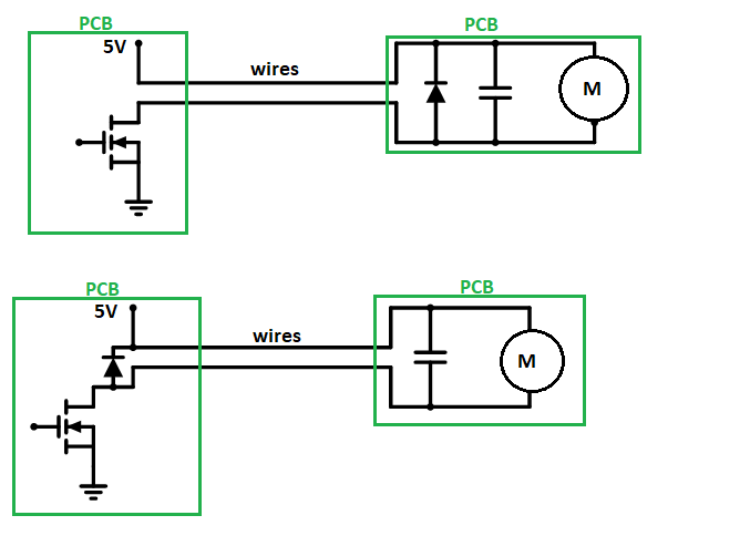
As I recently explained in this answer:
Determine adequate speed of flyback diode for a relay
The correct location is by the transistor; but that's not all, there should be a capacitor nearby as well.
How near, depends on the speed of the switch and the length of the loop formed by switch, diode and cap.
The difference may be small, or trivial, in many situations (where the loop is already small, the motor cables are short, the motor is the dominant inductance -- or relay or solenoid or etc.), but this advice applies generally, in all situations, from fast-switching SMPS to slow solenoids.
Regarding brush EMI, capacitors from each terminal, to motor chassis, and between terminals, is a common technique. Ferrite beads might also be used, on the terminals directly, or after the capacitors (or both), or common-mode choke, etc., depending on the situation. Note that capacitance here causes peak current to flow through the switch, the waveform becomes more complex: it's inductive at large time scales, but capacitive at short scales (give or take cable length). Using minimal values (perhaps a few nF?) may prove helpful. Further EMI mitigation can be useful for operation (snubbers to manage switch currents) as well as emissions (filters etc.), particularly if doing PWM.

