1
\$\begingroup\$

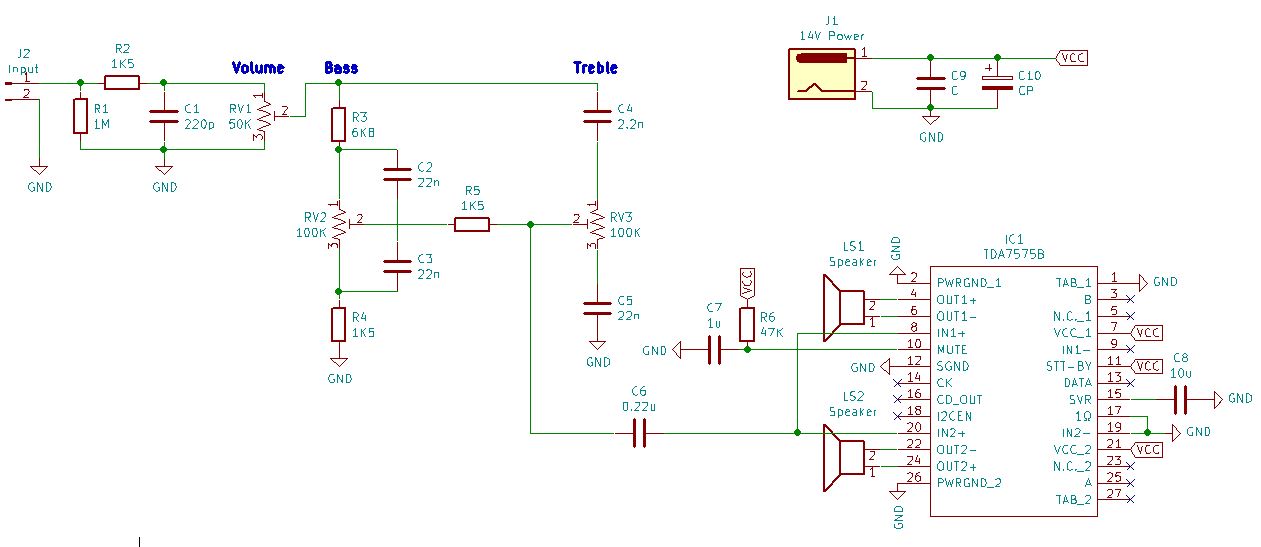
I am designing a PCB using the TDA7575B.

Schematic below.

I have a single input. It is passed through a filter (potentiometers, capacitors and resistors) for tone control and then fed to the TDA7575B.

I am confused about where to connect IN1- and IN2- so I grounded them. Is this connection of IN1- and IN2- correct?

enter image description here

\$\endgroup\$
3
  • \$\begingroup\$ Well, let us read the datasheet first: (1) TDA7575B 2 x 75W multifunction dual-bridge power amplifier with integrated digital diagnostics - ST st.com/resource/en/datasheet/tda7575b.pdf \$\endgroup\$
    – tlfong01
    Commented Dec 14, 2021 at 7:58
  • \$\begingroup\$ Then let us compare the datasheet's Fig 1 block diagram with your schematic. I forgot how to upload my comparison diagram to imgur. So cheat by putting it as an answer. \$\endgroup\$
    – tlfong01
    Commented Dec 14, 2021 at 8:16
  • \$\begingroup\$ Iffi - are we done here now? Do you have anything in my answer that doesn't make sense? \$\endgroup\$
    – Andy aka
    Commented Dec 15, 2021 at 16:14

2 Answers 2

1
\$\begingroup\$

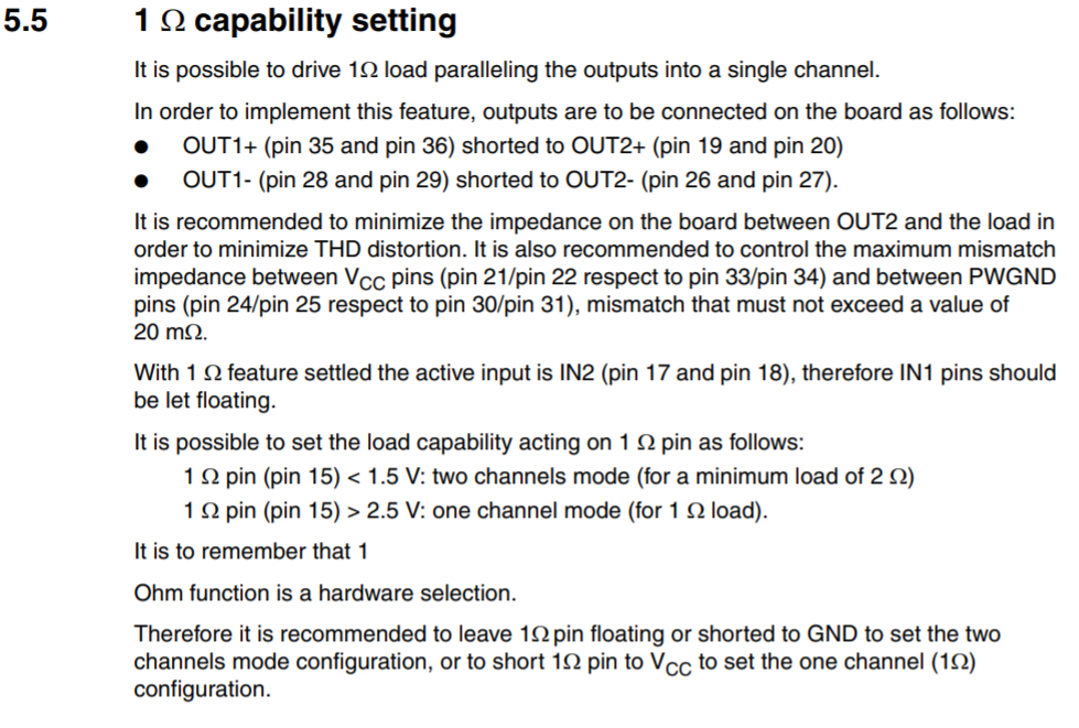
You really do need to read this section in the data sheet: -

enter image description here

You have the following connections to IN1 and IN2 in your schematic: -

  • IN1+ connected to the single ended input drive line
  • IN1- floating
  • IN2+ connected to the single ended input drive line
  • IN2- ground

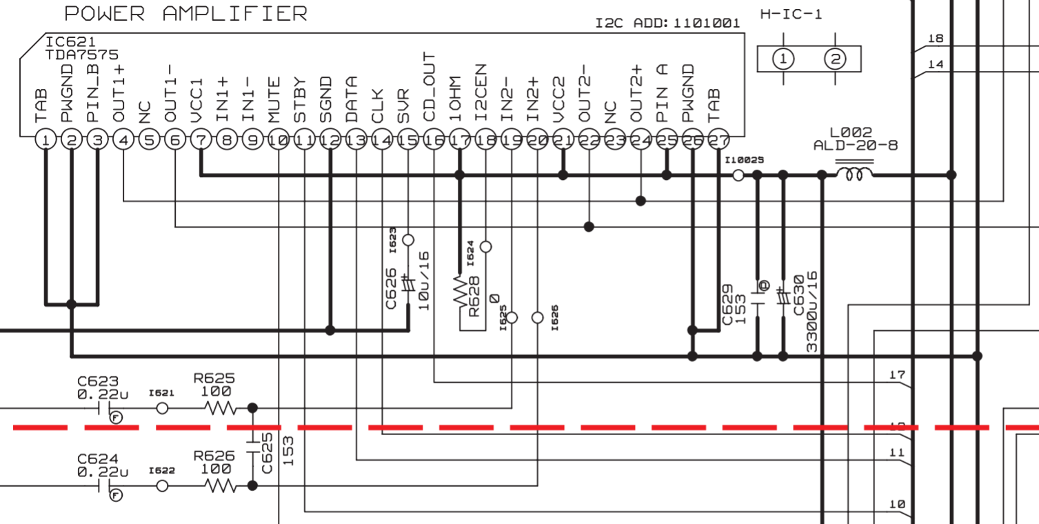
And this doesn't appear to tally with the data sheet extract above. Maybe you need a TDA7575 example schematic taken from here just to help you figure it out: -

enter image description here

The big point here is that the inputs are differential and not single ended (as you appear to be thinking of driving them). And, you need those input capacitors for each input. Don't skimp on that because it won't be guaranteed to work.

\$\endgroup\$
0
\$\begingroup\$

(1) Well, let us read the datasheet first: (1) TDA7575B 2 x 75W multifunction dual-bridge power amplifier with integrated digital diagnostics - ST https://www.st.com/resource/en/datasheet/tda7575b.pdf

(2) Then let us compare the datasheet's Fig 1 block diagram with your schematic. I forgot how to upload my comparison diagram to Imgur. So cheat by putting it as a quick and dirty answer.
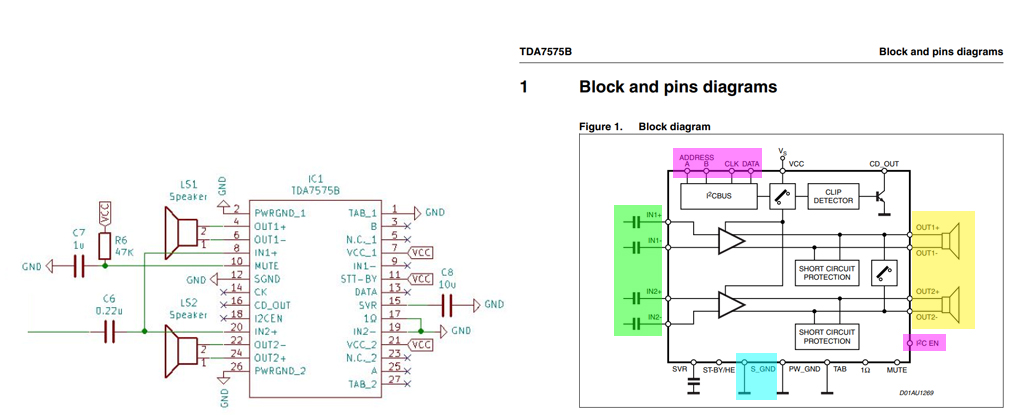
tda7575b

(3) ST7575B is I2C 75W digital power amp, with two channel differential inputs, and two channels 1Ω output.

(4) If you are playing with single channel, I would suggest to short both IN1 and IN2 to signal ground.

(5) And if also want single channel output, Datasheet Section 5.5 also suggests to parallel the two speakers together.

(6) Second part of Section 5.5 also suggests to (a) float IN1, or (b) short to ground.

\$\endgroup\$

Your Answer

By clicking “Post Your Answer”, you agree to our terms of service and acknowledge you have read our privacy policy.

Not the answer you're looking for? Browse other questions tagged or ask your own question.