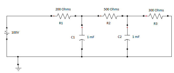
I'm trying to figure out why the time constant for charging each capacitor is different and how to calculate the time constant of each capacitor? I know how to find the time constant for a capacitor with single or multiple resistors but not with multiple capacitors.
5 Answers
The process is pretty simple. But the results are nuanced.
Let's label the first node as \$v_x\$ and the second as \$v_y\$. Then you have two KCL time-domain equations:
$$\begin{align*} \frac{v_x}{R_1}+\frac{v_x}{R_2}+\frac{\text{d}\,v_x}{\text{d}t}C_1 &= \frac{v_{_\text{CC}}}{R_1}+\frac{v_y}{R_2} \\\\ \frac{v_y}{R_2}+\frac{v_y}{R_3}+\frac{\text{d}\,v_y}{\text{d}t}C_2&=\frac{v_x}{R_2} \end{align*}$$
This is the same, in Laplace domain, as:
$$\begin{align*} \mathcal{L}\left\{v_x\right\}\left(\frac{1}{R_1\,C_1}+\frac{1}{R_2\,C_1}\right)+s\mathcal{L}\left\{v_x\right\} &= \frac{\mathcal{L}\left\{v_{_\text{CC}}\right\}}{R_1\,C_1}+\mathcal{L}\left\{v_y\right\}\frac{1}{R_2\,C_1} \\\\ \mathcal{L}\left\{v_y\right\}\left(\frac{1}{R_2\,C_2}+\frac{1}{R_3\,C_2}\right)+s\mathcal{L}\left\{v_y\right\}&=\mathcal{L}\left\{v_x\right\}\frac{1}{R_2\,C_2} \end{align*}$$
Or,
$$\begin{align*} V_x\left(\frac{1}{R_1\,C_1}+\frac{1}{R_2\,C_1}\right)+s\,V_x &= \frac{V_{_\text{CC}}}{R_1\,C_1}+V_y\frac{1}{R_2\,C_1} \\\\ V_y\left(\frac{1}{R_2\,C_2}+\frac{1}{R_3\,C_2}\right)+s\,V_y&=V_x\frac{1}{R_2\,C_2} \end{align*}$$
(Where \$V_x=\mathcal{L}\left\{v_x\right\}\$ and \$V_y=\mathcal{L}\left\{v_y\right\}\$.)
That's solvable (in the Laplace domain) using SymPy as:
var( 'r1 r2 r3 c1 c2 vx vy vcc s' )
eqvx = Eq( vx*( 1/r1/c1 + 1/r2/c1 ) + s*vx, vcc/r1/c1 + vy/r2/c1 )
eqvy = Eq( vy*( 1/r2/c2 + 1/r3/c2 ) + s*vy, vx/r2/c2 )
ans = solve( [ eqvx, eqvy ], [ vx, vy ] )
Since I wrote a small function for solving 2nd order transfer functions (documented elsewhere on this site), I can use \$V_{_\text{CC}}\$ as the "input" and find:
for y in ans: tf2( ans[y]/vcc )
 {omega: sqrt(r1 + r2 + r3)/(sqrt(c1)*sqrt(c2)*sqrt(r1)*sqrt(r2)*sqrt(r3)),
  zeta: (c1*r1*r2/2 + c1*r1*r3/2 + c2*r1*r3/2 + c2*r2*r3/2)/(sqrt(c1)*sqrt(c2)*sqrt(r1)*sqrt(r2)*sqrt(r3)*sqrt(r1 + r2 + r3)),
  P: [{A: c2*r2*r3/(c1*r1*r2 + c1*r1*r3 + c2*r1*r3 + c2*r2*r3), N: 1},
   {A: (r2 + r3)/(r1 + r2 + r3), N: 0}]}
 {omega: sqrt(r1 + r2 + r3)/(sqrt(c1)*sqrt(c2)*sqrt(r1)*sqrt(r2)*sqrt(r3)),
  zeta: (c1*r1*r2/2 + c1*r1*r3/2 + c2*r1*r3/2 + c2*r2*r3/2)/(sqrt(c1)*sqrt(c2)*sqrt(r1)*sqrt(r2)*sqrt(r3)*sqrt(r1 + r2 + r3)),
  P: [{A: r3/(r1 + r2 + r3), N: 0}]}
That's still in symbolic form, but it shows you a few details. One of them is that both nodes have the exact same \$\omega_{_0}\$ and \$\zeta\$ (or \$Q\$.) Another is that \$V_x\$ is a combination of a bandpass and a lowpass, while \$V_y\$ is just a lowpass.
Let's see the numerical results:
for y in ans: tf2((ans[y]/vcc).subs({r1:200,r2:500,r3:300,vcc:100,c1:1e-3,c2:1e-3}))
 {omega: 5.77350269189626,
  zeta: 1.06809799800081,
  P: [{A: 0.405405405405405, N: 1}, {A: 0.800000000000000, N: 0}]}
 {omega: 5.77350269189626,
  zeta: 1.06809799800081,
  P: [{A: 0.300000000000000, N: 0}]}
So \$\omega_{_0}\approx 5.7735\:\frac{\text{rad}}{\text{s}}\$ (\$f_{_0}\approx 918.86\:\text{mHz}\$) and \$\zeta\approx 1.0681\$. Neither node is under-damped (in fact, they can't be in this configuration regardless of part values), so the nodes shouldn't exhibit ringing in the time domain when the voltage source is applied.
The above can be put into a standard form as (reading from above that \$K_{x_1}\approx 0.450451\$, \$K_{x_0}=0.8\$, and \$K_{y_0}=0.3\$):
$$\begin{align*} \frac{\mathcal{L}\left\{v_x\right\}}{\mathcal{L}\left\{v_{_\text{CC}}\right\}}=\frac{V_x}{V_{_\text{CC}}}&=K_{x_1}\cdot\frac{2\zeta \omega_{_0}s}{s^2+2\zeta\omega_{_0}s+\omega_{_0}^2}+K_{x_0}\cdot\frac{\omega_{_0}^2}{s^2+2\zeta\omega_{_0}s+\omega_{_0}^2} \\\\ \frac{\mathcal{L}\left\{v_y\right\}}{\mathcal{L}\left\{v_{_\text{CC}}\right\}}=\frac{V_y}{V_{_\text{CC}}}&=K_{y_0}\cdot\frac{\omega_{_0}^2}{s^2+2\zeta\omega_{_0}s+\omega_{_0}^2} \end{align*}$$
Again, \$V_x\$ combines both bandpass and lowpass, while \$V_y\$ is just a lowpass.
You can re-phase the above as:
$$\begin{align*} \mathcal{L}\left\{v_x\right\}&=\mathcal{L}\left\{v_{_\text{CC}}\right\}\left[\frac{K_{x_1}\cdot 2\zeta \omega_{_0}s + K_{x_0}\cdot \omega_{_0}^2}{s^2+2\zeta\omega_{_0}s+\omega_{_0}^2}\right]&=\frac{100}{s}\cdot\left[\frac{15s + 80}{3s^2+37s+100}\right] \\\\ \mathcal{L}\left\{v_y\right\}&=\mathcal{L}\left\{v_{_\text{CC}}\right\}\left[\frac{K_{y_0}\cdot \omega_{_0}^2}{s^2+2\zeta\omega_{_0}s+\omega_{_0}^2}\right]&= \frac{100}{s}\cdot\left[\frac{30}{3s^2+37s+100}\right] \end{align*}$$
And take the inverse Laplace transforms to get the time-domain equations.
$$\begin{align*} v_x&=\mathcal{L}^{-1}\left\{\frac{100}{s}\cdot\left[\frac{15s + 80}{3s^2+37s+100}\right]\right\}=80-\frac{500}{13}\cdot e^{^{-4 \, t}}-\frac{540}{13}\cdot e^{^{-\frac{25}{3} t}} \\\\ v_y&=\mathcal{L}^{-1}\left\{\frac{100}{s}\cdot\left[\frac{30}{3s^2+37s+100}\right]\right\}=30-\frac{750}{13}\cdot e^{^{-4\, t}}+\frac{360}{13}\cdot e^{^{-\frac{25}{3} t}} \end{align*}$$
Note that, as I wrote in an earlier comment, you cannot mash up sums of two exponentials (with different time constants) into a single exponential and a single time constant.
Separately, you can just look by inspection to find the time constants above. The characteristic equation shown is \$3s^2+37s+100\$. This solves into two parts, \$\left(a_1 s - a_0\right)\cdot\left(b_1 s - b_0\right)\$. This means that \$a_1\cdot b_1=3\$. Let's assign \$a_1=3\$ and \$b_1=1\$. We also know that \$-a_1\cdot b_0-b_1\cdot a_0=-3\cdot b_0-a_0=37\$ and that \$a_0\cdot b_0=100\$. These two equations solve out as \$a_0=-25\$ and \$b_0=-4\$. Therefore, \$\left(3 s - 25\right)\cdot\left( s - 4\right)=3\cdot\left(s - \frac{25}{3}\right)\cdot\left( s - 4\right)\$. And there are the two constants we needed, \$-4\$ (corresponding to \$250\:\text{ms}\$) and \$-\frac{25}{3}\$ (corresponding to \$120\:\text{ms}\$), to use in the two powers of \$e\$.
The quadratic formula would get you to the same place, as well: \$\frac{-b\pm\sqrt{b^2-4\, a\, c}}{2\,a}\$. Just plug in the values: \$\frac{-37\pm\sqrt{37^2-4\,\cdot\, 3\,\cdot\, 100}}{2\,\cdot\, 3}=\frac{-37\pm\sqrt{1369-1200}}{6}=\frac{-37\pm\sqrt{169}}{6}=\frac{-37\pm 13}{6}\$ and here you get \$-\frac{25}{3}\$ and \$-4\$ for the roots.
You can also use Verbal Kint's technique, FACTs illustrated here, to find and sum two basic \$\tau\$s to supply the coefficient for \$s\$ (of 37, this comes from the sum of two \$\tau\$'s, one of \$160\:\text{ms}\$ and the other of \$210\:\text{ms}\$.) And the product of one of these and another \$\tau\$ developed by shorting a cap yields the \$s^2\$ coefficient.
Lots of ways to go. (Almost too many.)
Given \$f_{_0}\approx 918.86\:\text{mHz}\$ from above, you should expect things to pretty much settle out after about \$2\:\text{s}\$.
-
2\$\begingroup\$ thanks a lot for your very detailed comment, merry Christmas to you & your family :) \$\endgroup\$ Commented Dec 20, 2021 at 8:52
I'm trying to figure out why the time constant for charging each capacitor is different and how to calculate the time constant of each capacitor?
Here are some interesting facts: -
The value of a
fixed time constantseen in all simple RC circuits also extends to circuits with multiple resistors (and one capacitor). That time constant is fixed.Once you introduce another capacitor (as per your schematic), the "fixed" time constant mentality we have when there is only one capacitor, becomes flawed and inapplicable.
In effect, the time constants "change" with the evolution of time and, they cannot be regarded as simply "this RC" or "that RC" anymore.
You are looking for something in your circuit that doesn't exist anymore. Here's your circuit and I'm focussing on C1 and how it charges over time: -
If the charging voltage profile isn't a simple exponential related function then this cannot happen: -
Image above from this Q and A.
In other words, we expect for a simple RC that for each time constant period (defined by RC) to take the present capacitor voltage towards the final voltage by 63%. If this doesn't happen then we don't have a simple RC time constant any more.
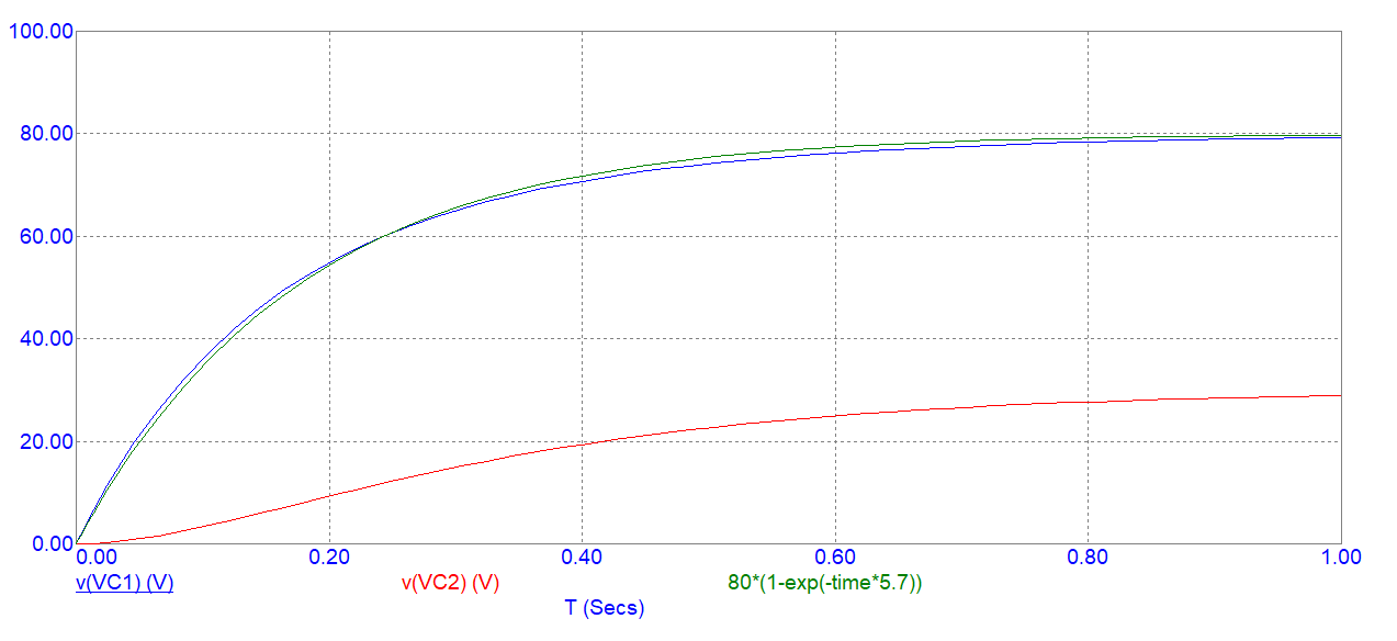
In a simulation we see this for the two capacitors charging: -
Compare green and blue. Green is a standard (single constant RC) waveform that I've tried to "best-fit" to the blue waveform - you can see there are unresolvable details and this makes the charging profile of C1 not tied to a fixed value of RC.
Red (C2 charging profile) is clearly not linked to a constant RC value.
-
1\$\begingroup\$ thank you very much, I clearly get the point now :) \$\endgroup\$ Commented Dec 17, 2021 at 16:27
Your circuit is a second order lowpass. Therefore, it is possible to bring the transfer function to the following standard form:
H(s)=Ao/[1+s(RxC1 +RyC2)+s².....]
Rx and Ry are combinations of R1, R2 and R3 - of course with the dimension "Ohm". From this you can derive (but for which purpose?) the two time constants RxC1=T1 and RyC2=T2.
-
\$\begingroup\$ thanks man, I was just curious and wanted to see whether we can combine the 2 time constants into 1 & why there exists 2 of them? \$\endgroup\$ Commented Dec 17, 2021 at 16:19
I believe each capacitor has it's own time constant and each of them is equal to τ = R_eqC. For your case τ1 = R1C1 and τ2 = (R1+R2)*C2
-
\$\begingroup\$ unfortunately it's not like you suppose, τ1 & τ2 are equal to 0.174s and 0.391s, which are not R1C1 & (R1+R2)C2, so I'm trying to find if there is a way to quantify the time constant \$\endgroup\$ Commented Dec 16, 2021 at 12:45
The simple explanation for this is as follows:
First simplify the circuit. The three resistors are in series, so the equivalent resistance is R1+R2+R3 = 1000 Ω.
Next, the capacitors are in parallel, so the nominal capacitance is C1+C2 = 2 mF.
The RC time constant for the whole circuit is then:
R·C = 1000 · (2·10-3) = 2 seconds.
-
1\$\begingroup\$ Sadly, it's not that easy. It can be viewed as a second order low pass filter which is alos not the same as just adding the capacity and resistor values. Plus: The third resistor is not in series to the capacitor but parallel to the last capacitor. \$\endgroup\$– kruemiCommented May 31, 2022 at 7:40


each time constantof relevance any more because of the interactions of multiple RC circuits. It stops becoming a meaningful quantity when you do this. If you solved the whole complex impedance of the circuit I'm sure you'd be able to see what I mean. \$\endgroup\$