1
\$\begingroup\$

I am reading through the book Practical Electronics for Inventors, specifically the section on capacitors. I read that capacitors in series will an have equivalent capacitance C with formula

$$ C=(1/C_1 + 1/C_2 + ... + 1/C_n)^{-1} $$

If we connect some capacitors in series to a voltage source Vs and let the capacitors charge up, the voltage drop across each capacitor will depend on the ratio of the individual capacitor to the equivalent series capacitance. The voltage drop across any of the capacitors is \$V_i = \frac{C}{C_i}V_s\$

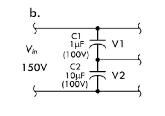
The author gives the following example problem:

enter image description here

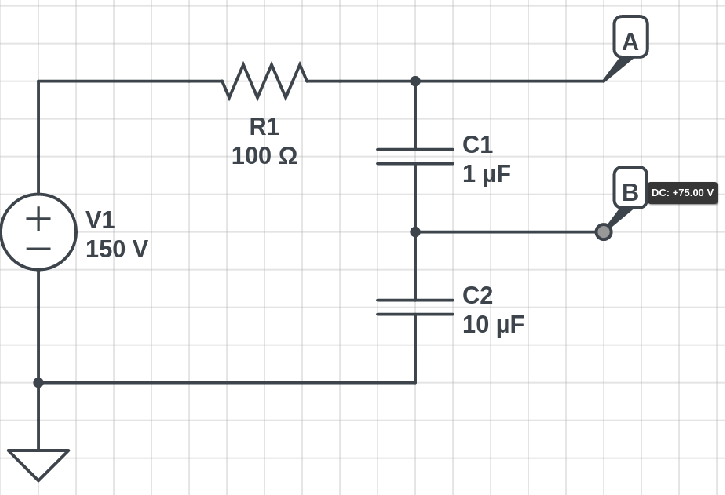
Using the equations above, the equivalent capacitance is C=0.91 microfarads and V1 = 136 V, V2 = 14 V. However, when I try to simulate this circuit in CircuitLab, I don't get the same result. No matter what I do, CircuitLab says there will be a 75V drop across the first capacitor. How can I replicate the textbook result in CircuitLab?

enter image description here

\$\endgroup\$
1
  • 1
    \$\begingroup\$ Try putting a really large resistor in parallel with each cap...like 100 Meg or such. That will let the simulator calculate a DC solution. The hugeness of the resistors will keep them from having any significant effect on the results. \$\endgroup\$
    – Kyle B
    Commented Dec 18, 2021 at 2:45

3 Answers 3

3
\$\begingroup\$

(CircuitLab developer here.) The problem is that you are evaluating at DC. You're unexpectedly seeing \$V(\text{B})=75 = \frac {1} {2} V(\text{A})\$. This happens because the simulator knows that \$V(\text{B})\$ is a floating node at DC (because capacitors look like open circuits at DC), and so in order to solve the circuit, it treats all capacitors as having some very high equivalent resistance. (In the SPICE world this would be called GMIN, a minimum conductance.) C1 and C2, while having different capacitances, have the same very large equivalent resistance at DC for this convergence approach, so without anything else affecting node B, they form a resistive voltage divider and you get 75 volts.

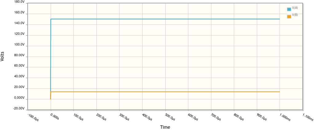
qrk's approach is correct: use a time-domain simulation (or frequency domain) to see the intended result.

In the time domain:

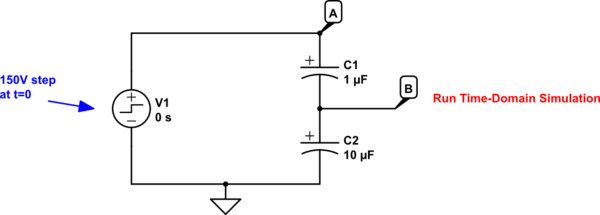
schematic

simulate this circuit – Schematic created using CircuitLab

You can open and run the simulation above and you'll get:

capacitors in series with CircuitLab in time domain

A frequency-domain simulation with V1 as the input source will give a similar result.

\$\endgroup\$
2
\$\begingroup\$

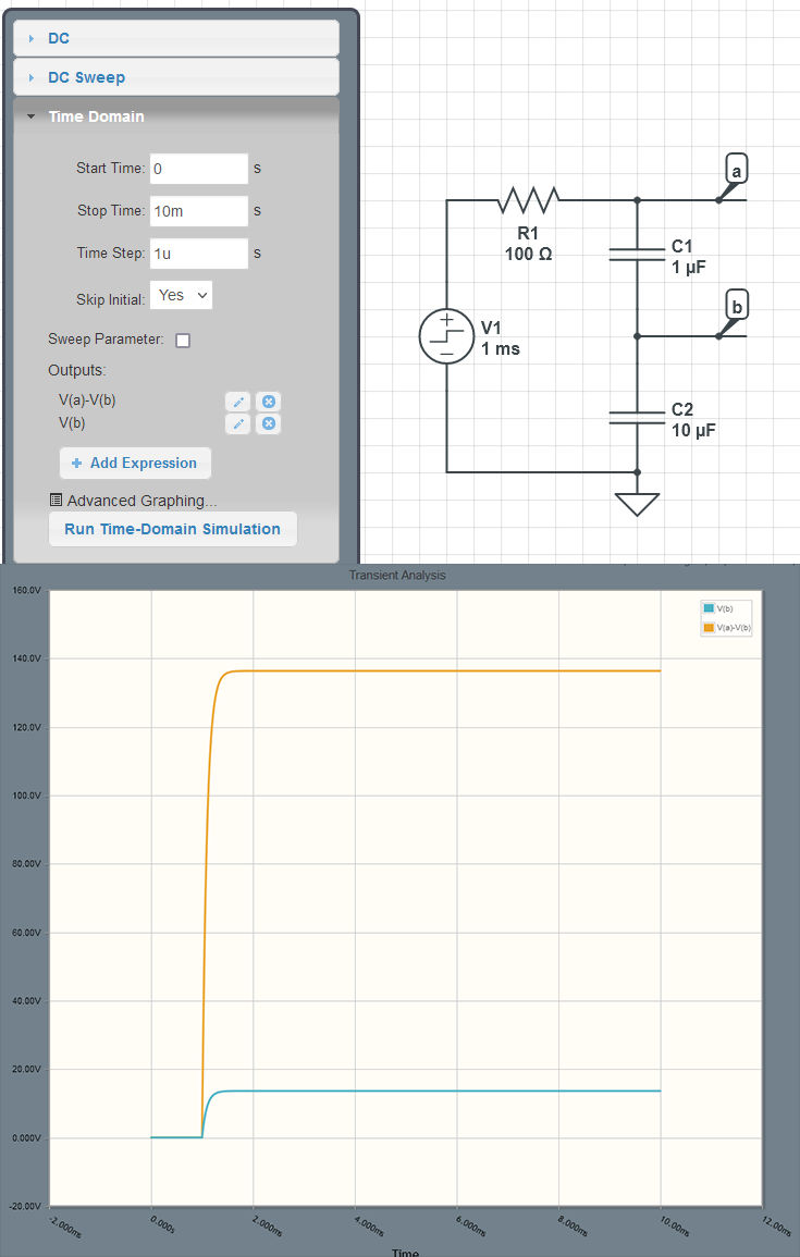
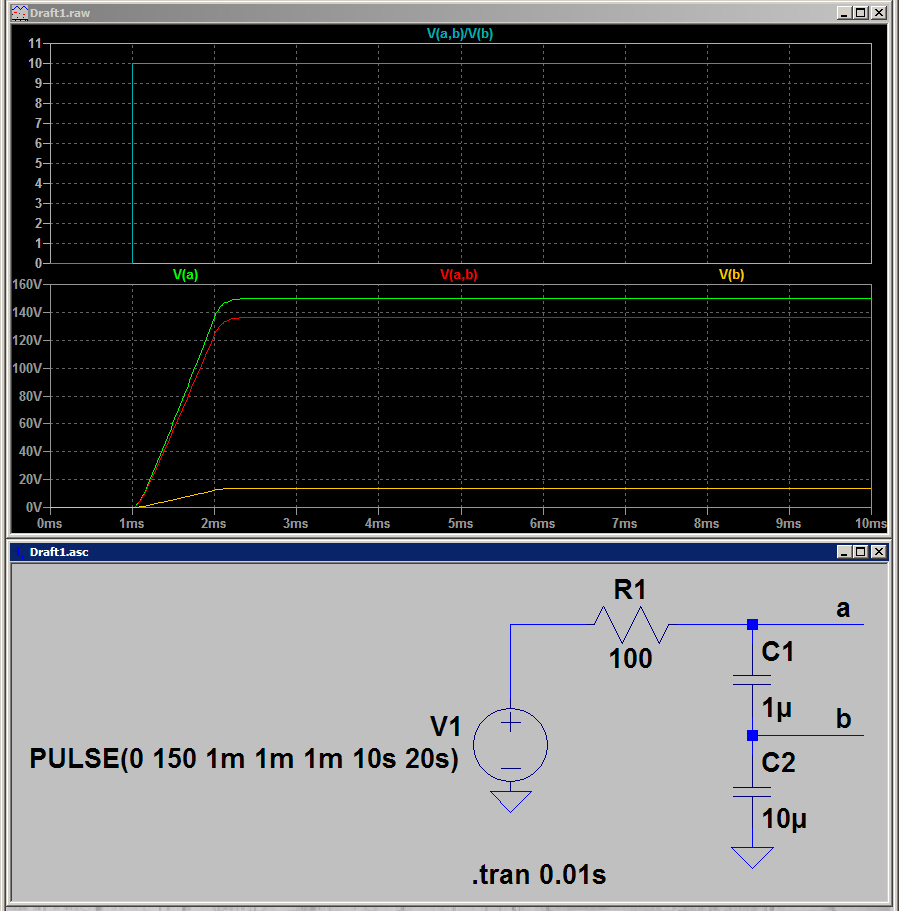
It may be due to the initial conditions (I'm not familiar how CircuitLab works). If you use a Voltage Step as your source with the pulse starting some time after time zero, you will get the intended results. This makes sure everything starts at a know condition.

[edit] Oops, Skip Initial should be No. I was playing around with CircuitLab to see how it responds. In this case, it made no difference.

enter image description here

I also did this in LTspice with the same results.

enter image description here

\$\endgroup\$
1
\$\begingroup\$

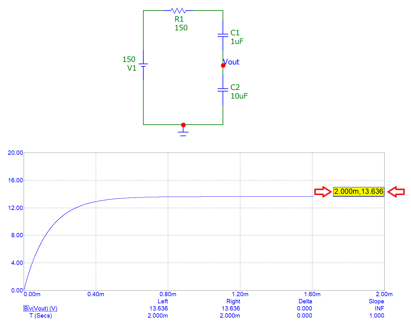
I bet your sim gives you 13.636 volts like mine: -

enter image description here

If it does, then that is the correct answer because the bigger capacitor (10 μF) will develop the smaller voltage in the ratio 11:1. Hence, 150 volts divided by 11 = 13.636363...

Look at it another way: the same number of electrons flow through each capacitor hence, they are charged identically. Given that Q = CV reveals that a bigger voltage is developed across the smaller value capacitor.

\$\endgroup\$

Your Answer

By clicking “Post Your Answer”, you agree to our terms of service and acknowledge you have read our privacy policy.

Not the answer you're looking for? Browse other questions tagged or ask your own question.