2
\$\begingroup\$

In this SMPS for white goods, the VCC pin 5 of U3 (LD7537) is initially fed from AC Mains through R54, R55 and R53 and once started it is fed from the auiliary winding (N2) of transformer (T1) through R66, R67 and D19. smps q10
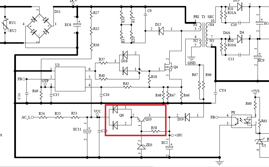
Why is there a transistor Q10 (MMBT4401) and the diode Q6 (BAV70) along the line from the auiliary winding to the VCC? The datasheet of U3 doesn't mention the use of such a circuit. What purpose does it serve and how does it work?

\$\endgroup\$
2
  • 1
    \$\begingroup\$ That is power supply for U1. It is permanently feeding U1. Chain of resistor R53-55 only for starting. Q6 prevents back current to transistor. \$\endgroup\$
    – user263983
    Commented Dec 24, 2021 at 11:29
  • 1
    \$\begingroup\$ ZD3 and Q10 form a crude voltage regulator (zener reference + emitter follower). Q6 blocks reverse current flow during startup. \$\endgroup\$ Commented Dec 24, 2021 at 11:30

2 Answers 2

3
\$\begingroup\$

Q10 and ZD3 for a classic circuit known as series pass voltage reulator. The output voltage will be equal to ZD3 mins the Q10 Vbe voltage.

\$\endgroup\$
2
\$\begingroup\$

U1 is permanently fed from auxillary winding via that voltage stabilizer. Chain of R53-55 just feed IC at starting main power.

\$\endgroup\$

Your Answer

By clicking “Post Your Answer”, you agree to our terms of service and acknowledge you have read our privacy policy.

Not the answer you're looking for? Browse other questions tagged or ask your own question.