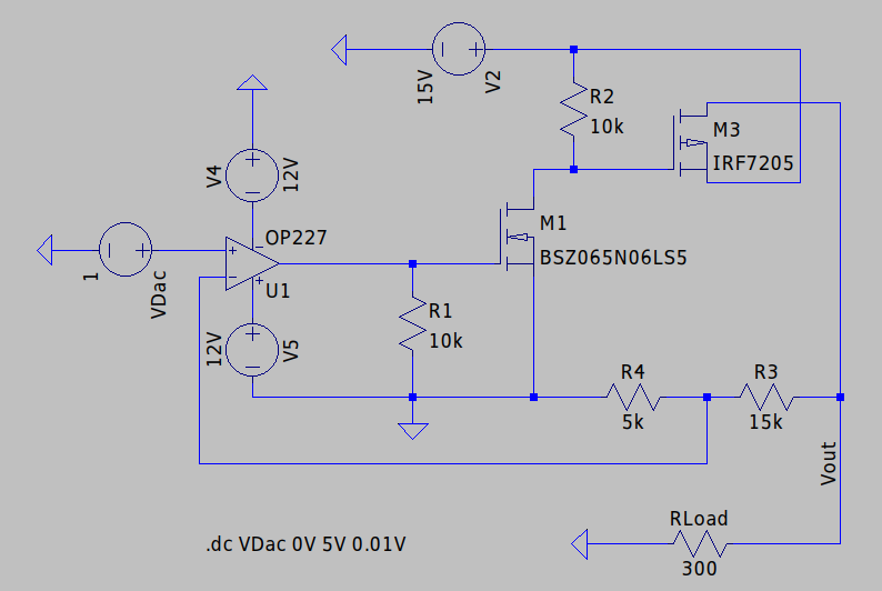
I'm trying to achieve a variable voltage supply where the voltage can be tuned by a DAC. The DAC is limited to ~3.3 V, but the design goal for the resulting voltage supply is V_out between 0 and 15 V and current up to 500 mA.
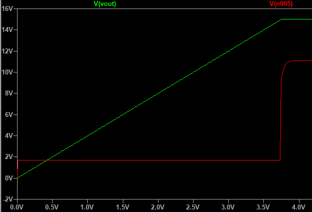
My current design consists of a driving a P-channel MOSFET with a N-channel MOSFET, which is controlled by an OpAmp. (The negative side of the load has to be connected to GND directly and so I cannot use a N-channel MOSFET directly and put it in the GND-path. Hence I used a P-channel MOSFET.) When I simulate this circuit in LTSpice I get the desired output, independent of the load (which I have modeled with a simple resistor here, and the DAC as a sweep between 0 and 5 V).
Now I have the following questions:
While it seems to work in LTSpice, I failed to reproduce the behavior with real components (OPA202, N-MOSFET ZVN4106FTA, P-MOSFET PJA3441). Instead, I only can get it to switch between 0 and 12 V, with no real linear behavior. I tried to use models with similar values in LTSpice - but is there anything in particular that I need to pay attention when choosing MOSFETs for this circuit, besides the max Vds, Vgs threshold and max. Isd?
Because the resistance of both MOSFETs is not linear with the Vgs, the voltage range for Vgs is extremely small and hence the voltage produced by the OpAmp needs to move within very tight boundaries (in the simulation above, the red line showing the OpAmp output voltage is almost always between 1.68 and 1.69 V for the whole range). I'm wondering: isn't this design prone for noise and instabilities, because there is no real stable operating point for the OpAmp? Do you have a suggestion for a good, maybe more linear alternative?


