1
\$\begingroup\$

I have a DC-DC Converter that is rated for an input of 9 to 36 V and an output of 12 V, 6 A.

When under no load, the DC-DC Converter outputs 12 V as expected. When under a load of one motors (0.037 A for some reason) the voltage drops to 8.4 V.

I have connected the +Vout to +Sense and -Vout to -Sense. I am also sure that my input (14 V, 10 Fully Charged NiMH Eneloop batteries in series) can supply the needed current.

I connected the output to a 100-ohm resistor. When I did, the voltage did not drop.

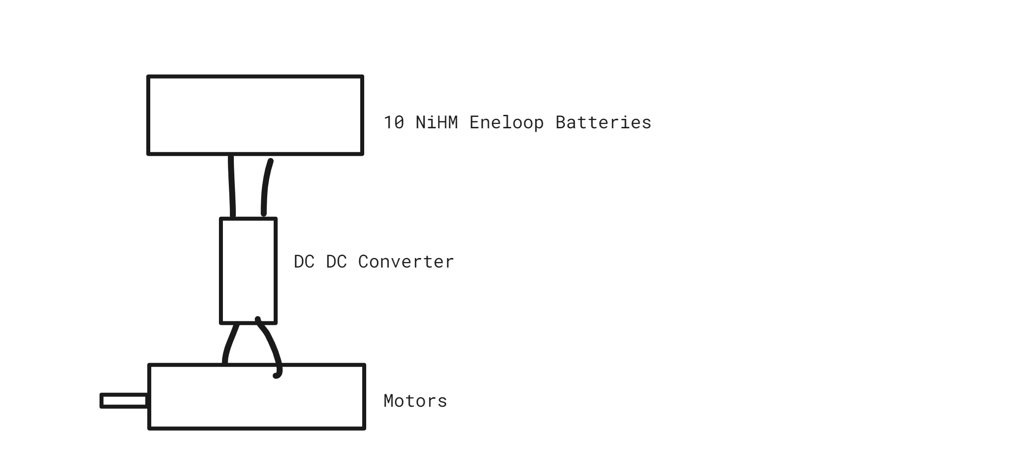
The circuit is pretty straight forward, but here is an image of it.

Simple Drawing of the Circuit

\$\endgroup\$
12
  • 2
    \$\begingroup\$ "around an amp probably" so measure! \$\endgroup\$ Commented Dec 28, 2021 at 0:21
  • \$\begingroup\$ @MarcusMüller I updated the question \$\endgroup\$
    – KetZoomer
    Commented Dec 28, 2021 at 0:27
  • \$\begingroup\$ @user263983, yes but as this is for a very brief time would it cause the DC-DC Converter to drop to 5.6v as long as the motors are moving? \$\endgroup\$
    – KetZoomer
    Commented Dec 28, 2021 at 0:32
  • 1
    \$\begingroup\$ @KetZoomer - Hi, Do you have an oscilloscope (min 2 channels) to capture the voltages at the DC-DC converter i/p & o/p simultaneously, when the converter is enabled via its ENA pin, with the motor already connected? If so, please capture that event & add the annotated trace to the question. (I don't know what that will show, I can only guess, but I would expect that to see good detail you'll need to have the 0 V position "off the bottom" of the display, and a sensitivity of 1 V/div or 2 V/div to show plenty of detail on the visible display.) Is there any Cin across the converter's i/p? Photos? \$\endgroup\$
    – SamGibson
    Commented Dec 29, 2021 at 1:09
  • 3
    \$\begingroup\$ @KetZoomer - Hi, "I do not have an oscilloscope" IMHO that's a large part of why there isn't yet enough info to understand what's happening :-( "Is there anything else I can try before that?" Apart from the Cin concern below, IMHO no. We could probably invent more tests, but we'd still need scope traces to understand those results too. (I asked about Cin and you didn't reply. I don't want to feel like I'm forcing you to reveal info that you don't want to, so I'll just point out that the PSU datasheet shows all spec with a Cin and leave it there.) Sincere good luck with the investigation! \$\endgroup\$
    – SamGibson
    Commented Dec 29, 2021 at 2:01

2 Answers 2

1
\$\begingroup\$

Measure your output voltage with an oscilloscope and determine if it's actually a solid 8.4V output under load or if it's oscillating.

If you are only doing the measurement with a multimeter it could be telling you the RMS value is 8.4V, but the output is actually fluctuating due to an instability.

\$\endgroup\$
1
  • \$\begingroup\$ I am afraid I have moved on from the project where the issue occurred. Thank you for the answer though! \$\endgroup\$
    – KetZoomer
    Commented Aug 19, 2023 at 0:49
0
\$\begingroup\$

I’m not sure about the difference between resistive load and inductive load.

Obviously, a motor is inductive.

The working current the motor get from the DC/DC output side is not same always.

There’s a peak raising current when motor rotates.

If the 0.037A current were measured by a meter when the motor was rotating?

If that was true, then I suggest you to check the continuous current in a oscilloscope in frequency field.

You’ll find the current ripple.

This will help you to diagnosis.

\$\endgroup\$

Your Answer

By clicking “Post Your Answer”, you agree to our terms of service and acknowledge you have read our privacy policy.

Not the answer you're looking for? Browse other questions tagged or ask your own question.