At the beginning - I'm a hobbyist not professional so be merciful and expect some basic knowledge holes I'm not aware off ;-)
I have some custom PCB with ESP32 uC powered up from Li-Ion with charging system built in. On the board there's also UART <-> USB translating circuit CH430C. It's used for communication with the chip and flashing.
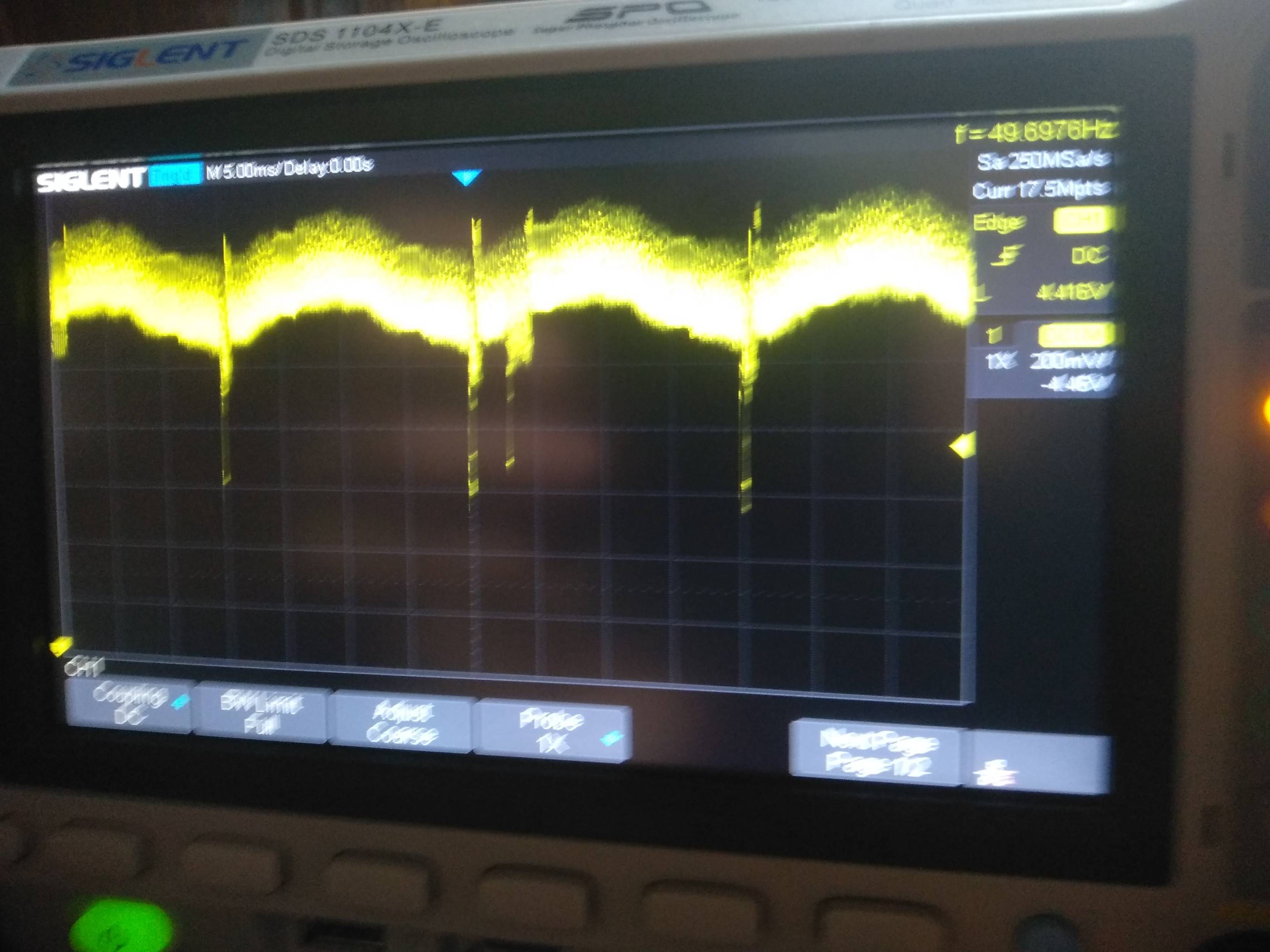
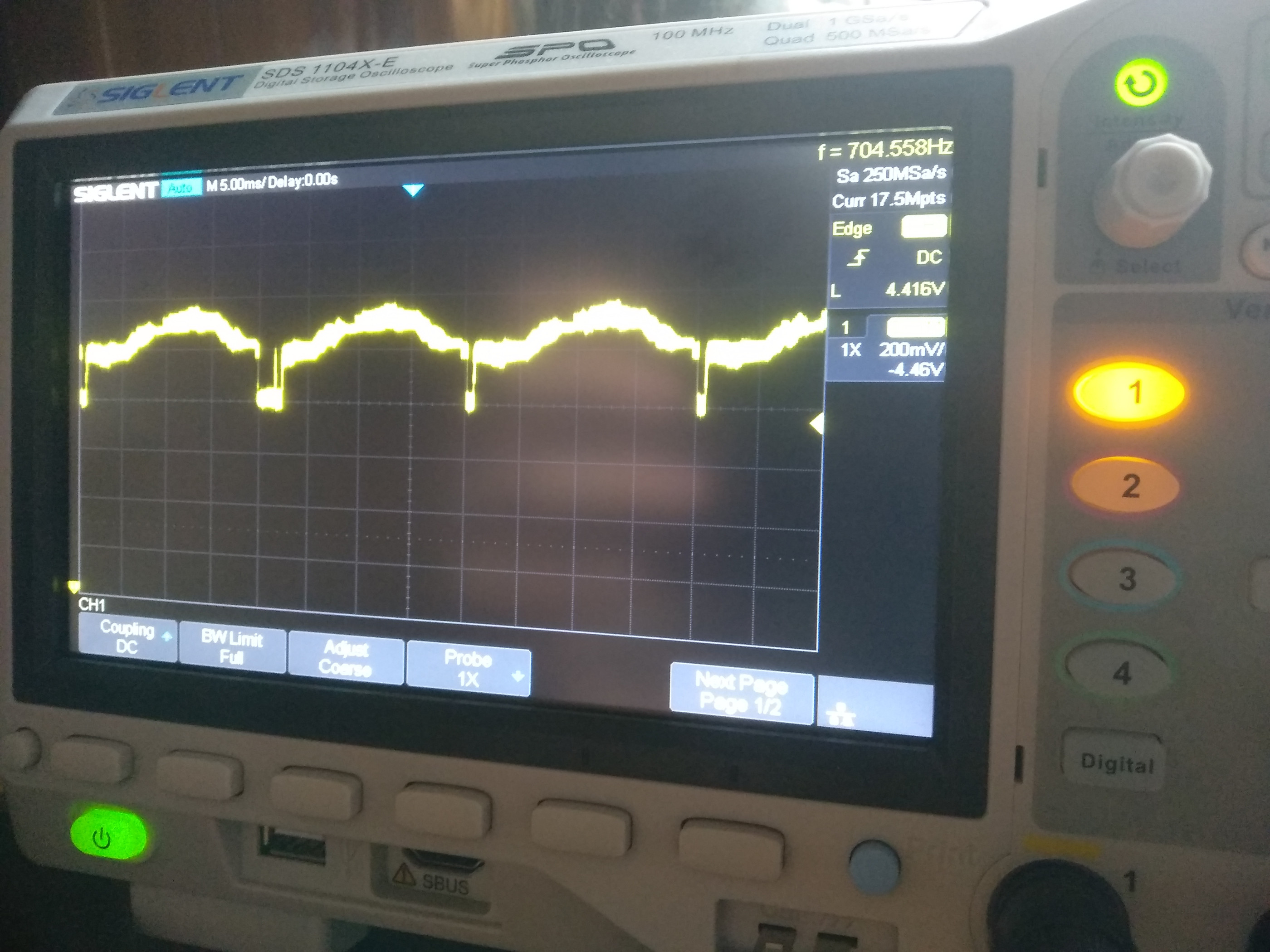
Almost everything at first glimpse works fine. Li-Ion is being charged and discharged nicely. CH340C communication works. RST and DTR signals work. ESP works. Problem is such that UART-USB communication works only for few minutes and then breaks - ESP most likely works tho. Oscilloscope readings suggest huge ground instability(1V).
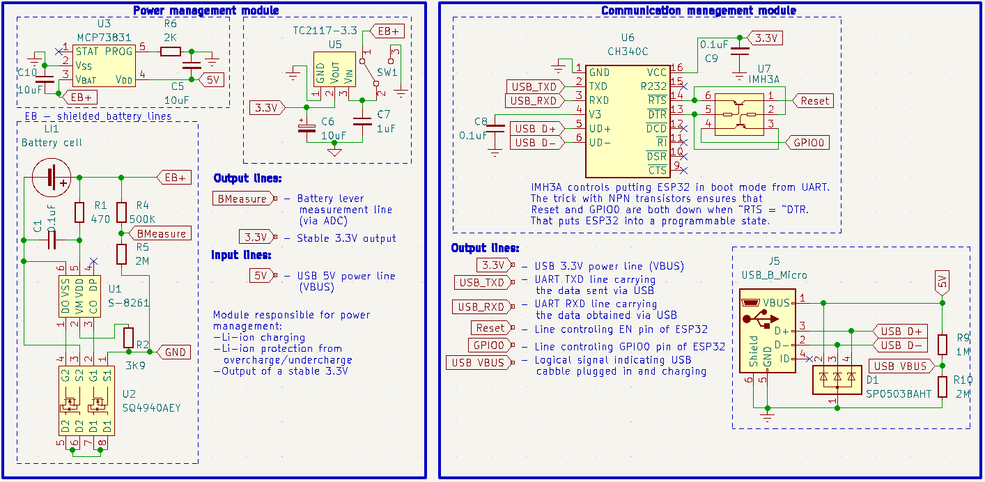
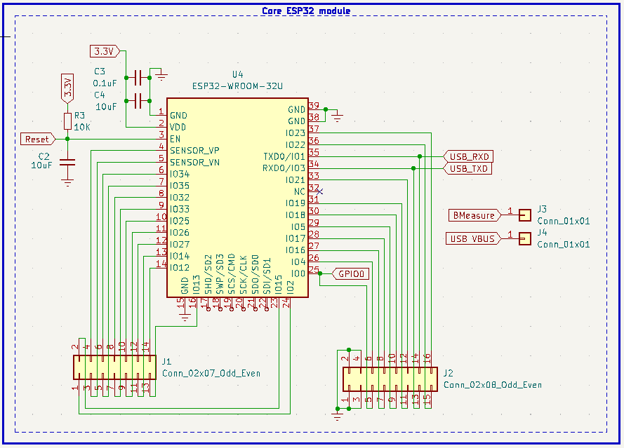
Schematic of the circuit is like this:
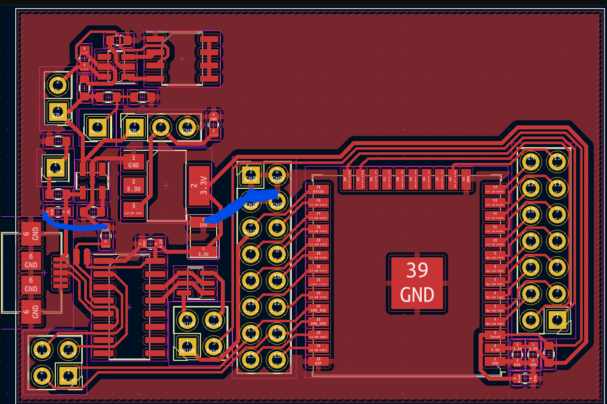
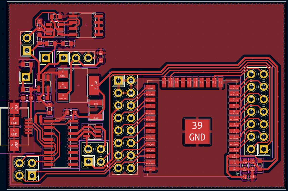
 Board looks like that:
 What exactly happens?
I connect the device to PC and start communication via picocom on Linux.
Device booted normally and started to print regular program logging.
After few minutes the communication broke tho with an error:
FATAL: read zero bytes from port
term_exitfunc: reset failed for dev UNKNOWN: Input/output error
Then I started to reset power circuit. Everything woke up(at least if it comes to voltages) but the device was not recognizable anymore. After tinkering few minutes and few resets more I was able to reproduce this behavior again. During circuit investigation with oscilloscope I've discovered that connecting probe's ground automatically fixes the problem. The same happens when I additionally connect ground from some other USB port of my PC to any place on the PCB (so when device is connected with port 1 GND D+ D- and 5V and with port 2 GND). Ground from the oscilloscope is relative to the PC ground - that's how it works - I think so at least. Anyway because of that I had trouble to measure what exactly happens with ground voltage on the board. I had to measure it with disconnecting the ground - voltage levels got shifted but at least the trend was visible.
Oscilloscope showed that when additional grounds are connected voltage on the +Bat is stable with subtle wave from the charger. When it gets disconnected the wave gets blurred and much more noisy with chronically distributed 1V peaks.
Desoldering the charger circuit helps as well so i assume that this is the culprit (or rather some bad PCB design). Can you tell me what actually happens there and how to fix it?
Thank you a lot for spending time over my somewhat long description ;-)

