1
\$\begingroup\$

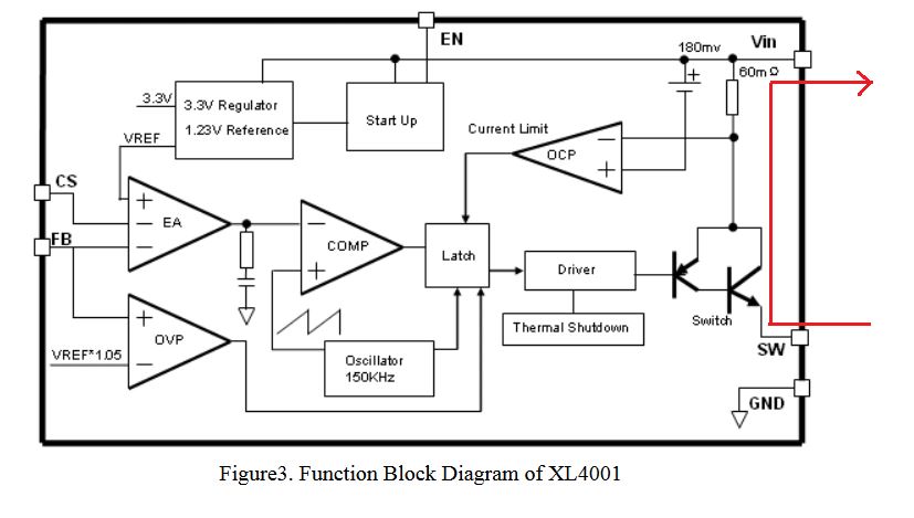
I am currently working on a prototype system that uses these 3w LED drivers (I am using the one with the picture at the right). It uses the XL4001E1 CC DC-DC converter capable of outputting 700mA to drive 3w LEDs, datasheet referred to found here.

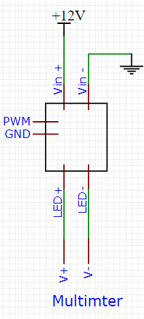
I was testing each of the modules (since I bought three) to see if they were working using a multimeter powering it with 12V supply. Due to carelessness, I accidentally powered one of the modules on the LED+- pins and connected the multimeter short circuit at the Vin+- pins. Schematic of my wirings are below for clarity:

enter image description here

While it was powered, I saw small sparks on the positive wires (I was using alligator clips between the components since I was testing). When I was measuring short circuit current across the Vin+-, I saw current dropping from 290mA to 270mA slowly (I was expecting constant 690-700mA). I was confused and only by that time I only realized that I was wiring it wrong. The module was heating but, thankfully, it didn't burn or explode.

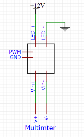
When I wired it correctly this time as shown here:

enter image description here

When I clipped the wire across the LED+- to the multimeter to take short circuit current readings, there was a small spark coming off from the positive wire of Vin+- and I didn't get any current reading. With my lack of understanding of some electronics concepts, here are my questions:

1.) What happened during the first scenario? I couldn't find the exact schematic diagram of this module, however, the datasheet does provide a schematic appropriate for LED driving applications which I think is somehow similar to the module. Here it is: enter image description here
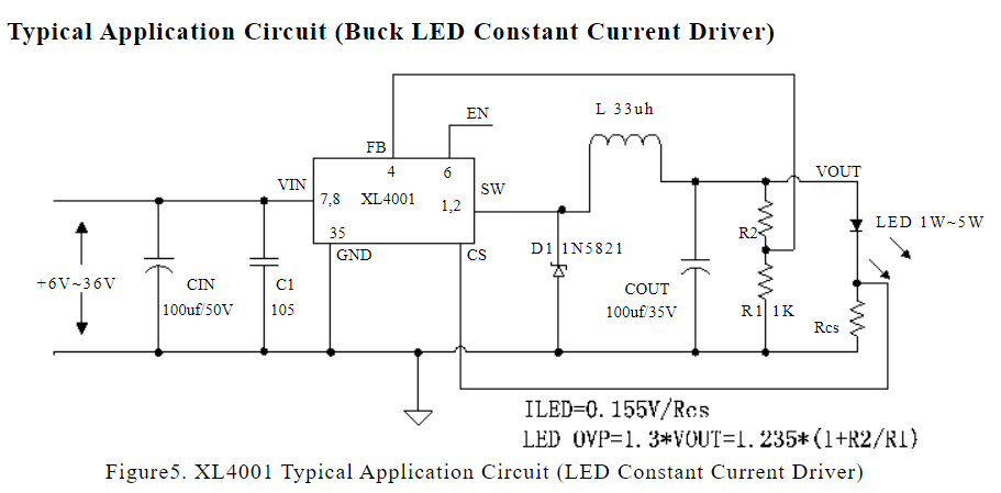
Is the SMD component damaged? How come the driver module significantly heated up? In the scenario the circuit was left longer as it is, could the capacitor have exploded?

2.) How can I properly check if the individual components are still working? Can the module still be salvaged by replacing some of the components?

\$\endgroup\$
4
  • \$\begingroup\$ What happened during the first scenario? - I think you know what happened (or what went wrong). Throw it away and buy a new one. \$\endgroup\$
    – Andy aka
    Commented Jan 7, 2022 at 9:08
  • 1
    \$\begingroup\$ Yes, I do know what I did wrong, but I was trying to ask the direct consequence of such scenario to somehow give me a better understanding on the workings of the circuit, and probably help me troubleshoot similar cases in the future. Sorry if I wasn't clear. \$\endgroup\$
    – Guorishix
    Commented Jan 7, 2022 at 9:14
  • \$\begingroup\$ You haven't actually said what happens when you use the module properly by connecting it to an LED, rather than trying to destroy it by short circuiting it. It may have survived your efforts to kill it. It's a myth that LEDs don't get hot. They do. If the LED is getting too hot, mount it on a heatsink. \$\endgroup\$
    – Simon B
    Commented Jan 7, 2022 at 12:06
  • \$\begingroup\$ The module provides constant current 700mA which suffice for powering the LEDs I am using. The LED heating mentioned was supposed to be the driver module. I did not expect the module to heat up significantly which led me to realize my careless mistake. \$\endgroup\$
    – Guorishix
    Commented Jan 7, 2022 at 12:35

1 Answer 1

2
\$\begingroup\$

Probably the controller was working, but as current polarity is inverted, was not limiting. The setup is simple, and the weak components are power transistor or current sensing resistor inside SMD. enter image description here

\$\endgroup\$
4
  • \$\begingroup\$ I see. I was supplying over 20A, I guess that explains the significant heat, but the current drop from the input doesn't make sense to me. \$\endgroup\$
    – Guorishix
    Commented Jan 7, 2022 at 9:23
  • \$\begingroup\$ you were supplying 20A to a circuit that should only consume a couple of hundred milliamps - that wasn't a safe method was it? Short circuit testing? That also sounds dangerous. Maybe your alligator clip wires were getting hot and making poor contact? Since we don't know precisely what you did, it is hard to give a clear answer. Don't test your constant current drivers by shorting the output - provide a reasonable load and measure the current. \$\endgroup\$
    – Kartman
    Commented Jan 7, 2022 at 9:59
  • \$\begingroup\$ In future, if you're working with circuitry that needs X Amps, then use a power supply with adjustable current limiting, and/or use a fuse. This will save you from melting things if there's a fault and avoid burning your house down. \$\endgroup\$
    – Kartman
    Commented Jan 7, 2022 at 9:59
  • \$\begingroup\$ I thought the constant current output would be fine when measuring short circuit current, in that case, I should have measured with the LEDs wired then. Also, wouldn't the driver module would only take much it can handle? I'm probably wrong on this one, please do correct me. Also, I won't be using that high current in my final designs as well, will probably just use 24v 5A units (with 3 of the modules in parallel providing just sufficient power) since currently I have 12V 20A for testing circuit prototypes. \$\endgroup\$
    – Guorishix
    Commented Jan 7, 2022 at 12:33

Your Answer

By clicking “Post Your Answer”, you agree to our terms of service and acknowledge you have read our privacy policy.

Not the answer you're looking for? Browse other questions tagged or ask your own question.