I know that the soaked paper spacer is there to protect oxide layer but how does it protect it and from whom does it protect it?
Why does the paper spacer need to be soaked in electrolyte and what happens if we replace the paper with a plastic film (which cannot be soaked in electrolyte?)
If I change the design a little bit and place two paper spacers and provide a little gap (vacuum) between two paper spacers then will there be an electric field between them? (This is a thought experiment, I was curious to know what if, so please neglect that capacitance value decreases if we generate the gap, I just wanted to know that will there be electric field between two paper space.)
-
1\$\begingroup\$ 3) should probably be asked as a separate question; it's not really related to the other two. \$\endgroup\$– HearthCommented Jan 9, 2022 at 18:14
-
4\$\begingroup\$ Electrolyte is one of electrodes. Second the aluminum foil. Oxide layer is insulator. \$\endgroup\$– user263983Commented Jan 9, 2022 at 18:14
-
3\$\begingroup\$ A liquid electrolyte will not maintain the physical separation, so the paper is there to be the physical separator. \$\endgroup\$– Andrew MortonCommented Jan 9, 2022 at 18:27
-
4\$\begingroup\$ The electrolyte makes it an electrolytic capacitor. If you change that to a plastic film, it will be a plastic film capacitor. \$\endgroup\$– JustmeCommented Jan 9, 2022 at 18:46
-
\$\begingroup\$ Did I not answer your question? \$\endgroup\$– D.A.S.Commented Jan 10, 2022 at 4:35
5 Answers
In an electrolytic capacitor, the oxide layer forms only between the positive plate and the electrolyte. It can be super-thin, even with 1930's manufacturing techniques, because it is formed chemically rather than mechanically. It is the thinness of this layer that gives electrolytic capacitors their very high capacitance to size ratio.
In an aluminum electrolytic capacitor*, the aluminum on the negative side is not insulated from the electrolyte**. This means that the negative plate is not just the aluminum part -- the actual working part of the negative plate is the electrolyte itself. This is to some extent why electrolytics tend to have high series resistance, and why they stop working when they dry out***.
So:
I know that the soaked paper spacer is there to protect oxide layer but how does it protect it and from whom does it protect it?
Your "knowledge" is, if not wrong, then not in the center of the target. The paper spacer is there to separate the positive from the negative plates so that the oxide layer can form. I suppose that if you stay in that head space then "from whom does it protect it" would be answered by "from the aluminum sheet in the negative plate"
Why does the paper spacer need to be soaked in electrolyte and what happens if we replace the paper with a plastic film (which cannot be soaked in electrolyte?)
Then you would just have a paper capacitor (they are, or were, a thing, occupying the same niche in electronics as film caps do today). The paper would be the dielectric, and as a consequence the dielectric layer would be much, much thicker and the capacitance would be lower.
If I change the design a little bit and place two paper spacers and provide a little gap (vacuum) between two paper spacers then will there be an electric field between them? (This is a thought experiment, I was curious to know what if, so please neglect that capacitance value decreases if we generate the gap, I just wanted to know that will there be electric field between two paper space.)
There would be an electric field going from one aluminum plate to the other, through both pieces of paper and the vacuum. The paper would only change the characteristics of the field as a consequence of its permittivity. You'd basically have a paper-vacuum-paper cap.
(Note that a vacuum cap is a thing, too -- search on "vacuum cap". They're used in high-power radio circuits; they have a lower breakdown voltage for their size than an air-dielectric cap, they don't produce ozone, and their characteristics don't change with humidity or altitude).
* And maybe all of them -- I only know for sure about aluminum electrolytics.
** In fact you can make electrolytics in a jar, and in further fact, really early radio technology (like, 1910's) use home-made electrolytics with commercial borax, fruit jars, and scrap aluminum sheet.
*** And, further, why they have lower temperature ratings than semiconductors, and why they have finite lifespans.
-
1\$\begingroup\$ For your one-asterisk footnote: This is true of standard aluminum electrolytics, but by oxidizing both plates you can make a non-polar aluminum electrolytic, which are commercially available though perhaps less so now with MLCCs continuing to get cheaper. I'm almost certain it's also true of aluminum-polymer and solid tantalum electrolytics, but I don't know about supercapacitors or niobium electrolytics. \$\endgroup\$– HearthCommented Jan 10, 2022 at 22:56
-
\$\begingroup\$ I know that non-polars are available, but not how they're made. Now I know a little bit more. \$\endgroup\$ Commented Jan 11, 2022 at 0:40
I think a heated discussion here is mostly due to some semantic differences in describing mechanical construction of the capacitors, rather than their functionality. I'll try to explain why @TimWescott and @user263983 were correct and lets see if we can find a consensus.
I won't be talking about laws of physics, because frankly, I don't know much. And I will be using only one, rather respectable source, because it is usually very careful with terminology, unlike manufacturing papers focused on production.
So, what is a capacitor?
Most capacitors contain at least two electrical conductors often in the form of metallic plates or surfaces separated by a dielectric medium. A conductor may be a foil, thin film, sintered bead of metal, or an electrolyte.
I emphasized "surface" here, because the thickness of the conductor is mostly irrelevant for the capacitance, which is defined only by permittivity of the dielectric, surface area, and a distance between plates (thickness of dielectric). Here are some quotes to supplement this:
the charge on each plate will be spread evenly in a surface charge layer of constant charge density
And from here:
According to Gauss’s law ... the entirety of the charge of the conductor resides on the surface.
From the above, it wouldn't be a stretch to say that the capacitor itself consists of two 2-dimensional surfaces and dielectric between them, the rest of it just electric terminals, housing and some insulation.
Of course, most people do not think in physical abstractions, that is why we are calling entire electronic device "a capacitor", just as we call the leads of electrolytic capacitors a "cathode" and an "anode". Once again, the wikipedia gets it right:
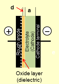
Note how the negative aluminum foil is called "Cathode terminal", rather than cathode. That is because in electrolytic capacitor the electrolyte IS a cathode, or rather a tiny boundary layer of it in contact with oxide dielectric. Therefore the negative foil does not play a role of capacitor plate. The size of it and the thickness of the electrolyte-permeated paper do not affect the capacitance, only ESR.
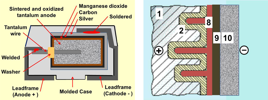
This is even more pronounced in tantalum electrolytic capacitors or aluminum capacitors with solid manganese dioxide electrolytes.
In these, there is no second aluminum foil at all. However there are two additional layers, graphite and silver, between electrolyte an a negative lead. Just as negative foil in aluminum capacitor, these are not cathodes but electrical connectors, or terminals. That was the whole point of the answers provided by @TimWescott and @user263983.
Although there are exotic nano-size fabricated materials with non-homegenous properties., this answer does not pretend to cover quantum physics nor nanotube electrical material science. It is just the fundamental truth to electrolytic capacitors or e-caps.
E-caps have improved more than a hundred-fold in my lifetime as an engineer in 1974, by making a conductor surface 3D with sputtered oxide materials with 100 times the surface area per cross-sectional area and thus 1% of the ESR compared to a standard e-cap.
2nd answer from journal reference as some users are posting false statements, with upvotes , downvoting correct answers and generally being ignorant without references to justify above.
Physical Model of the Capacitor:
An aluminum electrolytic capacitor, illustrated in Fig. 2 consists of;
- a cathode and anode made of aluminum foil,
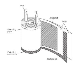
- a separator (electrolytic) paper, electrolyte, 3, and an aluminum oxide layer, which acts as the dielectric to the anode foil surface.
(NOTE MATERIALS ARE EITHER CONDUCTORS OR INSULATORS, Ideal materials cannot be both. T.S. )
When in contact with the electrolyte, the oxide layer possesses excellent insulation properties in the forward direction. Etching the foil magnifies the effective surface area, allowing for high capacitance in a small volume.
Since the oxide layer has rectifying properties, a capacitor has polarity. If both the anode and cathode foils have an oxide layer, the capacitor is bipolar. In this paper, we analyze ‘non-solid’ aluminum electrolytic capacitors in which the electrolytic paper is impregnated with a liquid electrolyte.
Another type of aluminum electrolytic capacitor uses a solid electrolyte.
Journal References:
-
1\$\begingroup\$ There really is no basis for considering something to be two materials when it's a chemical compound, particularly when we're talking about quantum effects like superconductivity that rely on the crystal structure that you can't get with just one of the elements alone. My point is just that you can't make blanket statements like "all materials are either conductors or insulators" unless you qualify it as "to a first approximation" or something along those lines. \$\endgroup\$– HearthCommented Jan 10, 2022 at 23:23
-
1\$\begingroup\$ When did I ever say anything about the dielectric being a conductor, or that there is only one foil layer in an electrolytic capacitor? All I'm saying is that there are corner cases to everything and that in my personal experience, being taught that everything is either in category X or category Y has more than once hindered my understanding of more advanced concepts down the line. It's fine to make simplifications, but say when you're simplifying. \$\endgroup\$– HearthCommented Jan 10, 2022 at 23:32
-
1\$\begingroup\$ When did I say anything about some way of making electrolytic capacitors? All I am talking about is the single overly general statement you made claiming that all materials are either insulators or conductors, which is an approximation at best and should be marked as such. \$\endgroup\$– HearthCommented Jan 10, 2022 at 23:35
-
1\$\begingroup\$ My complaint has nothing to do with capacitors. As I have stated several times, my complaint is solely about your unconditional statement that a material is either a conductor or an insulator, which is false. It's a fine simplification, particularly in this situation when talking about capacitors, but it should be stated that it's a simplification. \$\endgroup\$– HearthCommented Jan 11, 2022 at 0:15
-
1\$\begingroup\$ I repeat, I have personal experience with statements like this leading to significant difficulty down the line with understanding that things are more complicated than that. Even introductory texts should specify that the simplifications they make are simplifications, to avoid others having that same problem. \$\endgroup\$– HearthCommented Jan 11, 2022 at 0:26
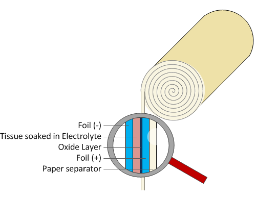
A standard aluminium electolytic capacitor still has two layers of metal foil acting as the conductors. If you left out the paper, then they would be pressing against each other. You need the paper to keep them apart until the oxide later is formed.
Then you have a plastic film capacitor. Polyester film capacitors exist, for example. They aren't electrolytic and don't behave like electrolytic capacitors.
You'd have a wierd capacitor where the insulator was two layers of paper and some vacuum. It probably wouldn't have a vey high capacitance, though.
-
1\$\begingroup\$ Electrolytic capacitor does NOT have two foil layers. See @user263983 comment for correct answer. \$\endgroup\$– MapleCommented Jan 9, 2022 at 19:03
-
1\$\begingroup\$ @Maple Yes, it does have two layers of foil. Do you think the only conductor for the cathode is a bit of wet paper? \$\endgroup\$– Simon BCommented Jan 9, 2022 at 19:09
-
\$\begingroup\$ That is not the point. The second conductor in electrolytic capacitor is always electrolyte, be it solid, liquid or gel. How you make connection from the capacitor lead to the electrolyte is irrelevant. It can be cathode foil, graphite (as in tantalum capacitors) or something else. The paper that you mentioned is not there to separate plates, it is to provide a medium to hold electrolyte "plate". Most important to understand is that electrolyte itself is in direct contact with oxide dielectric, despite paper being there. \$\endgroup\$– MapleCommented Jan 9, 2022 at 19:28
-
\$\begingroup\$ What this means is that both capacitor plates and dielectric gap between them are on the same side of the paper separator (when one is used). \$\endgroup\$– MapleCommented Jan 9, 2022 at 19:35
-
\$\begingroup\$ @Maple your comments of using the conductor as an electrolyte breaks the laws of physics. Journal reference proof please \$\endgroup\$– D.A.S.Commented Jan 10, 2022 at 22:35
The paper diffuses the dielectric evenly and provides a consistent gap which defines the breakdown voltage (BDV) which is derated with thermal and tolerance effects for the rated Voltage.
Adding air or vacuum in series with a dielectric constant, Dk=1 compared to a very high Dk electrolyte, puts a tiny capacitance in series, (which dominates the whole C value). It is well known from Arrhenius effects of 50%MTBF every 10'C rise for electrolytics and thus they are rated at max temp for something like 3000 hours or 3kh. This slowly evaporates the fluid, when heated so capacitors will eventually fail as the capacitance drops replaced by a gas and energy increases in the gap created by a gas and this in turn causes higher ESR as well as lower C as the electrolyte gradually partially evaporates. When 2 different C values are in series the smaller C or gap in this example has the most voltage drop. But bubbles are in parallel, so the effect is gradual until the lid bulges out.
Plastic has a lower Dk ~4 which would also lower C but with metallized film also yields a lower ESR making them operate at higher BW. Plastic also has a higher BDV per mm allowing smaller gaps to yield higher C values but still lower C density than electrolytic capacitors.


