0
\$\begingroup\$

I am using an LM2904 for my application.

One of the input voltages, the voltage at the negative terminal of the op-amp (Vin-), can vary from -400mV to 500 mV. However, the voltage at the positive terminal (Vin+) varies from 0 to 600 mV. The sensor producing these input voltages has differential outputs.

I am using a single supply of 5 V; the common-mode voltage of the op-amp is 0 to 3 V.

Do I need to consider common-mode voltage for both the inputs? How does common-mode voltage affect a differential amplifier?

\$\endgroup\$
6
  • 2
    \$\begingroup\$ What kind of schematic do you use ? \$\endgroup\$
    – Antonio51
    Commented Jan 20, 2022 at 11:56
  • 3
    \$\begingroup\$ one of the differential signals can vary from -400 mV to 500 mV. Ambiguous, do you mean 'one of V1 or V2 varies to -0.4 V'? If so, that violates the most negative the amp will accept, -0.3 V in the Absolute Maximums section of the data sheet. Please use consistent language in your question, differential signals are very prone to being misunderstood. Better yet, post a schematic with voltages marked. \$\endgroup\$
    – Neil_UK
    Commented Jan 20, 2022 at 12:00
  • \$\begingroup\$ I mean, one of the input voltage i. e. voltage at the negative terminal of opamp (Vin-) can vary from -400mV to 500mV. However, Voltage at positive terminal (Vin+) is varying from 0 to 600 mV. The sensor producing is differential inputs. \$\endgroup\$ Commented Jan 20, 2022 at 12:07
  • \$\begingroup\$ I am just confused, both the inputs of opamp should follow common mode voltage ? or it works with either of them \$\endgroup\$ Commented Jan 20, 2022 at 12:08
  • 1
    \$\begingroup\$ @MonicaBagade Please, add voltages specs in question as you made in comment beyond. \$\endgroup\$
    – Antonio51
    Commented Jan 20, 2022 at 13:25

2 Answers 2

2
\$\begingroup\$

The amplifier you have linked to is an ordinary opamp, not a 'differential amplifier'.

If you apply your sensor outputs to the input terminals of this amplifier, the output will be saturated at one rail or the other, its enormous gain will make it act more like a comparator than an amplifier.

You will need feedback to make it work as an amplifier with a defined gain. This feedback may well be designable so that your amplifier input voltages are within the amplifier specifications, even if one of your sensor outputs goes negative.

What is the output impedance of the sensor, both common and differential mode? What gain or output range do you require from the sensor amplifier? Both of these questions must be answered before a suitable amplifier can be designed around an LM2904.

\$\endgroup\$
0
\$\begingroup\$

How does common-mode voltage affect a differential amplifier?
Op-amp used: LM2904.

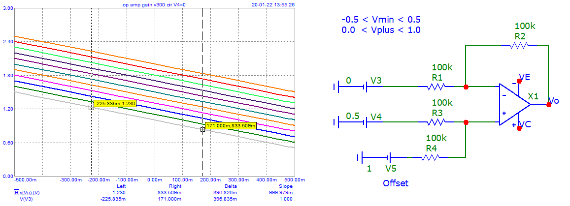
First, one must define a schematic that can be used for measuring.

And then you can "calculate" or "simulate" to see what happens ...

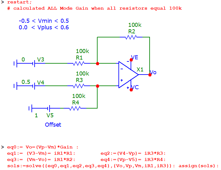
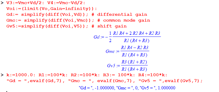
EDIT: added Maple sheet (EE&O).

enter image description here

enter image description here

Schematic : (EE&O) I may suggest this one, with your specs voltage inputs. (Vmin -> V3, Vplus -> V4)

enter image description here

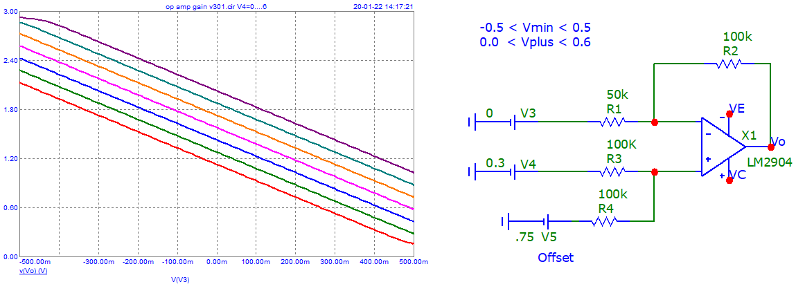
Or this one ... but Gmc is not equal to zero.

enter image description here

\$\endgroup\$
0

Your Answer

By clicking “Post Your Answer”, you agree to our terms of service and acknowledge you have read our privacy policy.

Not the answer you're looking for? Browse other questions tagged or ask your own question.