0
\$\begingroup\$

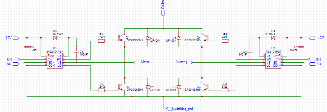
I am testing this H-Bridge circuit for driving a DC motor.

The Vdrive signal is a full wave rectified \$220 V_{RMS}\$, and I am using a PWM signal in the SD net to control the final voltage.

The motor I am using is rated for 2400 RPM at \$90 V_{DC}\$, power not specified but arround \$1 CV\$.

When I first started this circuit, let's just say the transistors didn't like it. The motor ran for about half a second before I saw a spark coming out of Q4 and immediately turned it off. When checking the circuit afterwards, both Q2 and Q4 had failed short, the resistance between the collector and emitter is smaller than I can measure.

My question is: why did they fail?

What I have considered:

Is the current way too high? It didn't trip the \$10A\$ breaker, and these transistors are rated for \$20A\$ sustained and \$60A\$ pulses.

Is there a overvoltage? The Vdrive voltage peaks at about \$311 V\$. Maybe the back EMF when the transistors are turned off exceeds their \$650V\$ maximum rated?

enter image description here

\$\endgroup\$
15
  • 2
    \$\begingroup\$ I can't say that this is the problem, but a breaker is generally far too slow to protect semiconductors, so it wouldn't be surprising to have transistors destroyed without the breaker tripping. \$\endgroup\$
    – GodJihyo
    Commented Jan 20, 2022 at 17:00
  • 1
    \$\begingroup\$ How are you switching it? Are you aware the high side IGBT bootstrap voltage is only available from switching the low side, and with limitations on duty cycle? Please show oscillograms of Vice and Vge for each transistor. \$\endgroup\$
    – winny
    Commented Jan 20, 2022 at 17:03
  • 1
    \$\begingroup\$ Were you maintaining some PWM activity? Or could it have gone to 100%? \$\endgroup\$ Commented Jan 20, 2022 at 17:03
  • 1
    \$\begingroup\$ Just to rule something out: What do IN1 and IN2 look like? Is the dead time of 500 ns the IRS2104s provide enough? Have you looked at the actual switching signals on an oscilloscope? \$\endgroup\$
    – ocrdu
    Commented Jan 20, 2022 at 17:08
  • 1
    \$\begingroup\$ @rubemnobre I'm inclined to think 1200uF was oversized. But I believe you need something : you have diodes to dump inductive spikes onto the supply rail ... without any smoothing, what does that do? ... I'd suggest 50 or 100uF. (Also note there are motor rated breakers, which don't trip so easily on surge current. But if you're soft starting, ramping up speed, you won't need those) \$\endgroup\$
    – user16324
    Commented Jan 20, 2022 at 18:32

1 Answer 1

1
\$\begingroup\$

With a peak voltage > 325V to a boost cap into a UF4004 less than 1 Ohm might be excessive capacitance. 100 nF is around 13 ohms at 100kHz and lower at the harmonics resulting in a peak current of 32A at 100Khz. But for the 1st pulse from a square wave, the current will depend on the ESR of the cap and series R for RC risetime. Ic=CdV/dt-V/ESR

Consider that this cap only needs to be much greater than the gate load to create a boost voltage. Consider a much smaller cap like < 10nF.

But on second thought, you are probably using PWM much lower and so the rate of Vrms frequency and thus acceleration current of the motor df/dt can be as much as 10 x the rated full load current (depending on Vpk/DCR) might have been the cause of failure.

Normally VFD's will modulate PWM with a constant V/f ratio as it speeds up.

Finally, always verify your parasitic crosstalk from mutual capacitance and ESL inductance do not skew the dead-time of your commutation. Test with a resistive load such as a tungsten lamp before validating your design assumptions on a motor.

\$\endgroup\$
4
  • \$\begingroup\$ Valid point about the capacitor, but in this specific case I actually used a frequency of only 1 kHz (I know it's slow), so I don't think this is the problem. The acceleration makes sense, though. How could I solve this? Maybe a ramp in the duty cycle? \$\endgroup\$
    – rubemnobre
    Commented Jan 20, 2022 at 17:45
  • 1
    \$\begingroup\$ yes you need a controlled acceleration, however you do it. Lookup VFD. \$\endgroup\$
    – D.A.S.
    Commented Jan 20, 2022 at 17:46
  • \$\begingroup\$ wikiwand.com/en/Variable-frequency_drive \$\endgroup\$
    – D.A.S.
    Commented Jan 20, 2022 at 17:49
  • \$\begingroup\$ you mention V/f ratio and VFD, in my experience these are used for driving AC motors, but I am driving a DC motor and the H-Bridge is for alternating the direction. Are these relevant for my case too? \$\endgroup\$
    – rubemnobre
    Commented Jan 20, 2022 at 18:07

Your Answer

By clicking “Post Your Answer”, you agree to our terms of service and acknowledge you have read our privacy policy.

Not the answer you're looking for? Browse other questions tagged or ask your own question.