I am currently working on a PIC16F5244.
I am currently trying to correct a problem that despite my multiple searches and tests is still present. When I mount a new PIC16 on my PCB, I can program it, several times even. When I change the program, no matter how small the change is, I cannot reinject the program.
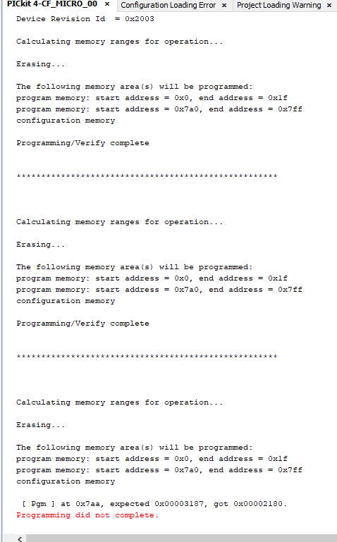
In the screenshot you will find attached, you will see the following error: "at 0x7aa, expected 0x00003187, got 0x00002180. Programming did not complete."
Below, you will find the program that I inject:
//CONFIG1
#pragma config FEXTOSC = OFF     // External Oscillator Mode Selection bits->Oscillator not enabled
#pragma config RSTOSC = HFINTOSC_1MHZ     // Power-up Default Value for COSC bits->HFINTOSC (1 MHz)
#pragma config CLKOUTEN = OFF     // Clock Out Enable bit->CLKOUT function is disabled; I/O function on RA4
#pragma config VDDAR = HI     // VDD Range Analog Calibration Selection bit->Internal analog systems are calibrated for operation between VDD = 2.3V - 5.5V

//CONFIG2
#pragma config MCLRE = EXTMCLR     // Master Clear Enable bit->If LVP = 0, MCLR pin is MCLR; If LVP = 1, RA3 pin function is MCLR
#pragma config PWRTS = PWRT_OFF     // Power-up Timer Selection bits->PWRT is disabled
#pragma config WDTE = OFF     // WDT Operating Mode bits->WDT disabled; SEN is ignored
#pragma config BOREN = ON     // Brown-out Reset Enable bits->Brown-out Reset Enabled, SBOREN bit is ignored
#pragma config BORV = LO     // Brown-out Reset Voltage Selection bit->Brown-out Reset Voltage (VBOR) set to 1.9V
#pragma config PPS1WAY = ON     // PPSLOCKED One-Way Set Enable bit->The PPSLOCKED bit can be cleared and set only once in software
#pragma config STVREN = ON     // Stack Overflow/Underflow Reset Enable bit->Stack Overflow or Underflow will cause a reset

//CONFIG4
#pragma config BBSIZE = BB512     // Boot Block Size Selection bits->512 words boot block size
#pragma config BBEN = OFF     // Boot Block Enable bit->Boot Block is disabled
#pragma config SAFEN = OFF     // SAF Enable bit->SAF is disabled
#pragma config WRTAPP = OFF     // Application Block Write Protection bit->Application Block is not write-protected
#pragma config WRTB = OFF     // Boot Block Write Protection bit->Boot Block is not write-protected
#pragma config WRTC = OFF     // Configuration Registers Write Protection bit->Configuration Registers are not write-protected
#pragma config WRTSAF = OFF     // Storage Area Flash (SAF) Write Protection bit->SAF is not write-protected
#pragma config LVP = ON     // Low Voltage Programming Enable bit->Low Voltage programming enabled. MCLR/Vpp pin function is MCLR. MCLRE Configuration bit is ignored.

//CONFIG5
#pragma config CP = OFF     // User Program Flash Memory Code Protection bit->User Program Flash Memory code protection is disabled

#include <xc.h>
#include "system.h"


bool value = false;
bool test = true;

void main(void)
{
    //SYSTEM_Initialize();

    while(1)
    {
        if (!value){
            value = true;
        }
    }
}
Below you will find the program with the modification :
//SAME PRAGMA + INCLUDE
bool value = false;
bool test = true;

void main(void)
{
    //SYSTEM_Initialize();

    while(1)
    {
        if (!value){
            value = true;
        }

        if(test)
           test = !test;
    }
}
If I try to reinject the original program the error is the same.
I also add the electrical schematic of my PCB in attachment. Following research on the net, I tried several configurations on the VPP/MCLR wire. Nothing changes. I left the minimum on the PCB to limit the possible causes of failure In my last test, I removed D1 to leave a direct link on the VPP/MCLR wire
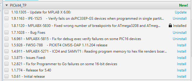
To finish and hoping to have given you the maximum of information, here is my software configuration: MPLAX V5.5 XC8 V2.35 PIC16F1xxx_DFP Packs V1.9.163 PICKit 4 (Version + packs in attachment) Tool Option : Mode entry : Use Low Voltage Method : Apply Vpp b4 Vdd Power : Power target : enabled Voltage lvl : 4.8V
Thanking you and hoping to find a solution to this problem that complicates my life for several days


LVP\$\endgroup\$LVP OFFbut always the same problem... Programming tool : Pickit 4 \$\endgroup\$