7
\$\begingroup\$

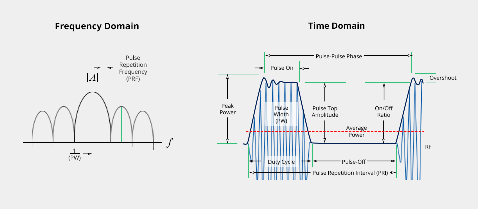
I'm looking to measure the signal width of electronic signals (device under test, DUT). The problem is that these signals have a quite short pulse width which would require me to use a GHz oscilloscope which I don't have (and can not afford at the moment). I might be able to borrow a GHz oscilloscope to have a look at the signals, but want to make sure the signals are somewhat in the range of a few nanoseconds. I found the following image (see below), where from the spectrum of the signals the pulse width (PW) can be read out.

Time Domain vs Spectrum of Signal, source: signalhound.com

Would it be possible to use a (cheap USB) spectrum analyser (like the ldtz 35MHz to 4.4 GHz) to get a approximate feeling of the pulse width (with a accuaracy of around +/- 50%)?

The DUT produces signals of around 1-3 ns (I need to adjust the signals width) with the outut voltage of the pulses are 0 V (low) to 5 V (low). The DUT is provided by a 10 MHz Trigger source, the trigger source could be exchanged for something faster, till up to around 60 MHz. I created the DUT, all coponents are placed on a PCB and had a look with a 100 MHz oscilloscope at one example circuit which produces a 3.2 ns wide signal, it did look good...

Or would there be some simple alternatives to create a circuit to convert the pulse width of the nanosecond pulses to an analog voltage? Like with comparators?

I'm very grateful for any input, thank you very much to everyone have a look at my question.

\$\endgroup\$
0

2 Answers 2

11
\$\begingroup\$

Given that your signal has constant, known amplitude, there's actually a much simpler way: Filter it with an RC low-pass that has a time constant greater than the maximum expected signal width. As long as the time constant is large enough, you can assume that the capacitor's voltage is negligible compared to the 5V pulse, meaning that the pulse will inject a constant current into the capacitor. The charge, and therefore the capacitor's voltage, is then directly proportional to the pulse width. The voltage on the capacitor will decay slowly enough for you to measure it with a 100MHz oscilloscope.

With 500 Ohms and 100pF, you'll get 100mV per nanosecond of pulse width (right after the pulse). Tau is 50ns, so if you measure the voltage 50ns after the pulse is over, you'll be at 63mV/ns due to the exponential decay. That's well within the capabilities of a 100MHz scope.

Make sure to use a non-inductive resistor, ideally an SMD thick film part.

\$\endgroup\$
1
  • \$\begingroup\$ equally adequate method with added parts. \$\endgroup\$
    – D.A.S.
    Commented Jan 23, 2022 at 15:12
7
\$\begingroup\$

Certainly but you need to match the capacitance of your intended load or include the load and tap a small signal without adding any capacitance then you can get <<1% accuracy.

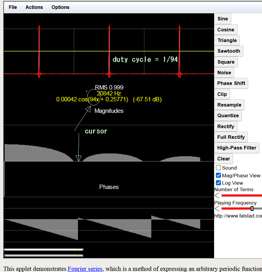
There will be harmonics starting from f=10 MHz with a null at 1 GHz for 1 ns pulse-width at 50% amplitude threshold or aka., the PW50.

Then another null due to rise/fall time cancellation f=0.35/tr . I hope you are using CML.

Just use something like 1K series into the 50 ohm to drive the coax.

You could also simply grab a 1k resistor with a 10:1 probe and plug that into your USB SA and sniff the signal with the wire resistor.

Anecdotal:

I once had to do the same for 50% duty cycle trimming and used a spectrum analyzer and made a table of values for the 2nd harmonic 5%, 1%, 0.1%, so it was easy to measure with a probe near the signal without even touching it... just getting the relative ratio of 1st-2nd f in dB.

For those that do not know Fourier transforms enter image description here http://www.falstad.com/fourier/

\$\endgroup\$

Your Answer

By clicking “Post Your Answer”, you agree to our terms of service and acknowledge you have read our privacy policy.

Not the answer you're looking for? Browse other questions tagged or ask your own question.