I've been working on a hobby project and recently got help from this community on input power source switching.
I'm supplying my AVR based PCB with USB or LiPo battery power (with an MCP73831 based charging circuit). The MIC2877 boost converter has a "Bidirectional True Load Disconnect" feature when the EN pin is pulled to ground. I was hoping to disconnect the load from V_BATT when USB power is provided.
I'm trying to eliminate nearly all current draw from V_BATT because as I understand it, if there's load present on the V_BATT line during charging it could prevent the battery from charging fully.
The current solution I have is to disable the boost converter with a high-side P-channel MOSFET, but I have no idea how to select an adequate MOSFET nor how to select appropriate resistors.
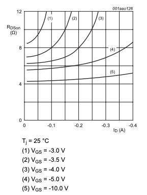
As of now, I'm considering a BSS84 because it's cheap, readily available, there's an Eagle symbol for it, and the datasheet says it's logic level compatible. The EN pin pulls 1.5 uA. The BSS84 has an Rds(on) of roughly 8.5 ohms at Vgs = -3.0V near that current.
I don't have any reason to believe that's acceptable, but it felt kind of reasonable. Is this an adequate MOSFET for this purpose?
I put a 2.2 KOhm resistor on the gate of the MOSFET to reduce the inrush current drawn by the capacitance of the MOSFET, but this resistor selection was somewhat arbitrary. Do I need R14? If so, how do I select a resistance for this application?
I added R12 because I assumed something was going to need to pull the gate to ground when V_USB was disconnected. I'm not really sure why I felt that way, but I assumed that if the transistor has capacitance then there must be a need for electrons to escape once the current source was removed so I stuck it on there. Is R12 necessary? How do you pick the right resistance for it?
Finally, I added R13 believing that when Q2 was switched off, a pulldown resistor would be necessary so the EN pin wasn't "floating?" Do I need R13? How do you pick a resistance for that resistor?


