1
\$\begingroup\$

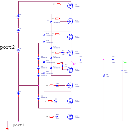
Here is a five-level inverter circuit, simulated by Pspice:

enter image description here

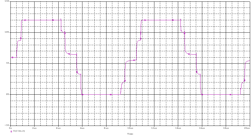
When I connect the GND to port1 the simulation results are correct, and the output wave is a five-level step wave, which contains the voltage levels of 0 V, 3 V, 6 V, 9 V, and 12 V.

Here is the simulation result when GND is connected to port1:

enter image description here

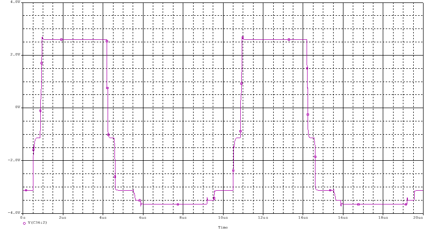
However, when GND is connected to port2, instead of showing a five-level step wave contating -6 V, -3 V, 0 V, 3 V, and 6 V the simulation result are different, as below:

enter image description here

Does the GND port only influence the level of the voltage? How does this happen?

\$\endgroup\$
3
  • \$\begingroup\$ It's still correct. What you need to check is the volatge difference between two points. A simple example would be dual supply with 10V each. If you put ground in the middle, the top is 10V and bottom is -10V. However if you put the ground at the negative terminal of the bottom battery then the top is 20V and bottom is 0V. And you can see that the voltage difference between any two points is not changed. \$\endgroup\$
    – hana
    Commented Jan 29, 2022 at 8:02
  • \$\begingroup\$ emmm,I think the voltage difference changes in the second diagram. As I only change the GND connection, the result waveform should be the same as the first one. However, the second one shows different waveform compared to the first one. \$\endgroup\$
    – Linda Yu
    Commented Jan 29, 2022 at 11:18
  • 2
    \$\begingroup\$ The two graphs have different scales, in the first case (port1=gnd) the voltage span is 12V, and in the second the voltage span is only 6V. It's more than just the expected voltage offset caused by changing the gnd reference point. Somehow there seems to be a gain artifact. Could there be some flaw in the transistor model? Some hidden connection to ground inside the models perhaps? \$\endgroup\$
    – MarkU
    Commented Jan 30, 2022 at 0:33

1 Answer 1

1
\$\begingroup\$

The voltage probe gives the difference between its current point with respect to 0 reference (what we're calling GND). So in the first simulation, it simulated from output to port 1. In the second simulation, it's showing results from output to port 2, not with respect to port 1 anymore.

\$\endgroup\$

Your Answer

By clicking “Post Your Answer”, you agree to our terms of service and acknowledge you have read our privacy policy.

Not the answer you're looking for? Browse other questions tagged or ask your own question.