1
\$\begingroup\$

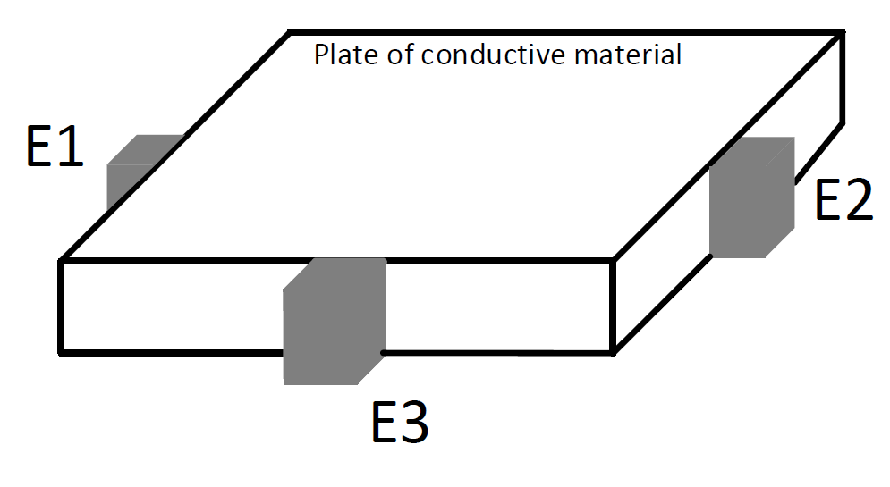
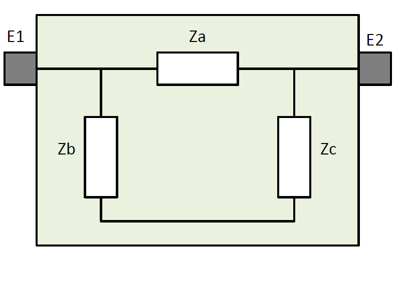
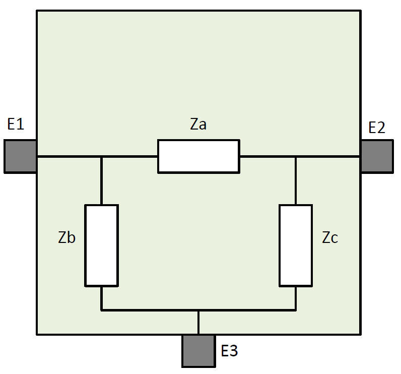
Imagine we have a square-shaped conductive material to which we connect 3 electrodes E1, E2, and E3. Suppose we assume for this material a 'pi' two-port network model with impedances Za, Zb, and Zc (figure below), i.e., an electrical impedance between each pair of electrodes.

I was wondering what would happen if we take an LCR meter and measure impedance between electrodes E1 and and E2 while E3 is not connected to anything. Would we measure just Za or instead Za in parallel to (Zb and Zc) in series?

enter image description here

Plate illustration:

enter image description here

\$\endgroup\$
5
  • \$\begingroup\$ What do you mean by "case"? For the configuration, you can imagine a square plate of some conductive material to which we add 3 electrodes. Unless we use some measurement device, such as LCR meter in my case, the system (plate+electrodes) is not connected to anything. \$\endgroup\$
    – Likely
    Commented Feb 2, 2022 at 12:24
  • \$\begingroup\$ Ok. Material is "distributed" along with the 2 points of measurement. And the "length" of elementary "wires" is not equal ... So, it appears a bit difficult to draw any conclusion (before one makes an integral calculus on this "area"). I would make a test with a foil of carbon to "test" this. Or a simulation with a "number" of resistors ... Wait and see ... \$\endgroup\$
    – Antonio51
    Commented Feb 3, 2022 at 20:48
  • \$\begingroup\$ I have divided the square shape conductive into a network of 1k resistors (11 lines by 11 columns). Points E1 and E2 on line 3 (Z of E1->E2 = 1.960 k). On line 4, Z=1.898k. On line 5, 1.888k. Etc ... So, Z is dependent on positions of "connections". \$\endgroup\$
    – Antonio51
    Commented Feb 3, 2022 at 21:33
  • \$\begingroup\$ Measured also between E1 and E3. E3 on column 5 (low center). E1 on line 3 -> Z=1.849k. E1 on line 4 -> Z=1.747k. E1 on line 5 -> 1.663k. Here is my setup. i.sstatic.net/hiTey.png \$\endgroup\$
    – Antonio51
    Commented Feb 4, 2022 at 5:20
  • \$\begingroup\$ Just consider that one has a 3-port system with variables I1, I3, I2. Measure than currents when one set V1=1, V3,=0, V2=0. The currents are the partial admittance matrix, with some equalities ... \$\endgroup\$
    – Antonio51
    Commented Feb 4, 2022 at 6:14

4 Answers 4

1
\$\begingroup\$

Obviously you expect something rigorous which proves the already repeated claim "you must take into the resistance between E1 and E2 all parts of your model, also the series of Zb and Zc"

We must start by checking is the delta model made of three resistors Za, Zb and Zc at all useful. Physicists fortunately have proven that the plate can be modeled with a big resistor network (= a finite element model) and it can be used to solve how currents and voltages actually distribute inside the plate. The result becomes more accurate if the sizes of the elements are reduced (and the number of the elements is increased).

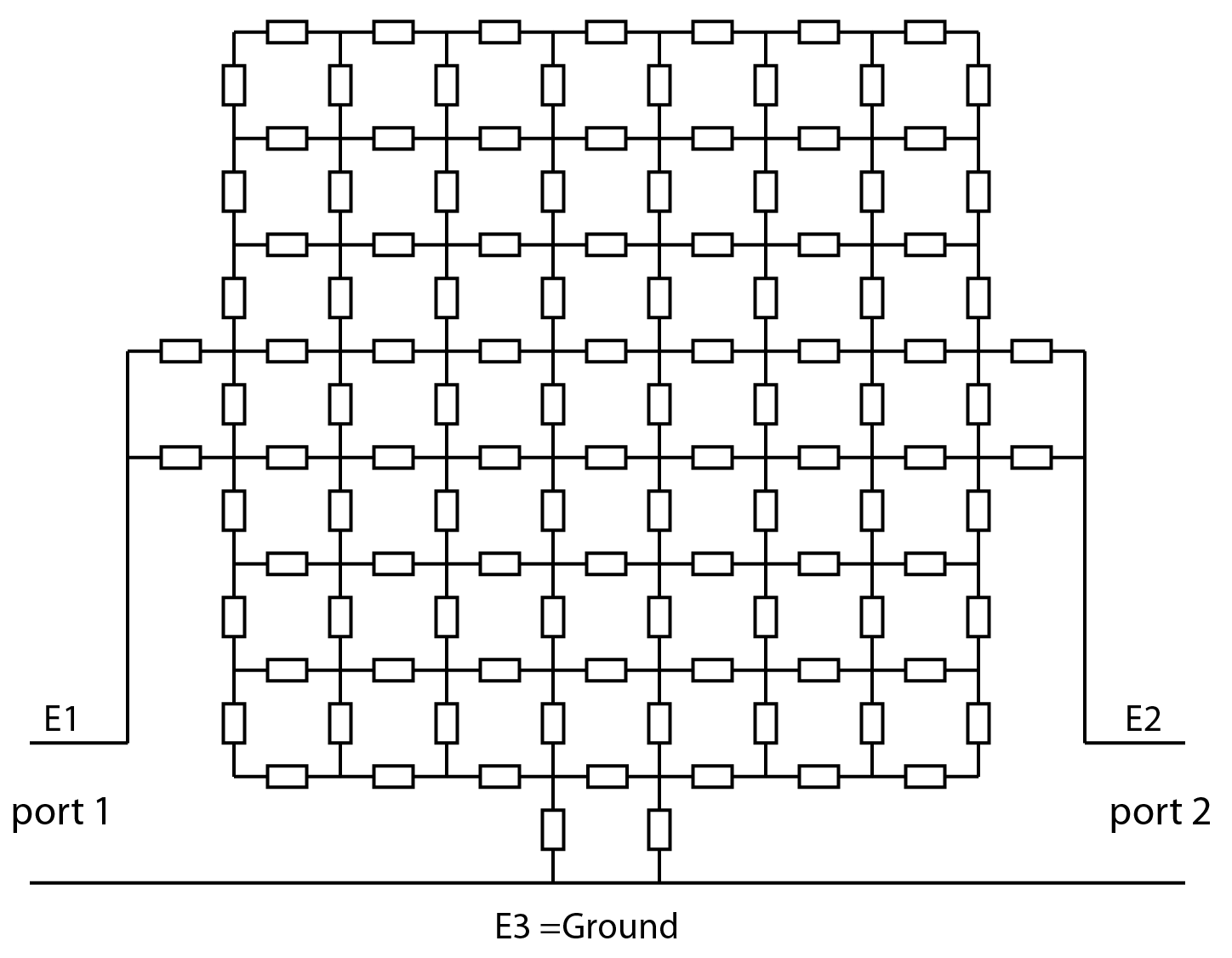
A coarse model:

enter image description here

I named terminal E3 a GND because the circuit theory allows one node to be the GND. That makes the model of the plate essentially to a 2 port.

After believing that a resistor network really can present the plate as accurately as wanted (by increasing the number of elements) we can apply a circuit theory fact: Any passive resistor 2-port can be reduced to an equivalent three resistor 2-port; as well to a vye as to a delta:

enter image description here

Proving it needs some tricky manipulations of the circuit equation matrices. I must skip it, but university level circuit theory books have it.

When it's shown that a delta circuit model behaves like your plate when the plate is used as a circuit we have no excuses to forget any of the three resistors in the model when we calculate the resistance between E1 and E2.

You actually wrote of impedances, not resistances. If the frequency is high enough all circuit models become finally useless because they do not take into the account wave effects including radiation. At reasonably low frequency the reduction to a delta is OK, but the impedances depend on the frequency.

\$\endgroup\$
4
  • \$\begingroup\$ For your coarse model, I was wondering why did you choose to connect each electrode at two points (of the resistive network) instead of one. Otherwise, I think I get your point. Basically, ALL the resistors ARE THERE, whether we connect E3 or not. \$\endgroup\$
    – Likely
    Commented Feb 8, 2022 at 23:38
  • \$\begingroup\$ Do you have a reference, or keyword/phrase to search with, for converting a resistive network to a 3 resistor 2-port? \$\endgroup\$
    – Likely
    Commented Feb 8, 2022 at 23:40
  • \$\begingroup\$ The conversion can happen only if there's only 2 ports fed by voltage sources, but the network can be as complex as possible. Let those 2 ports have names A and B. let A and B have external voltage sources Va and Vb. Let they have in KVL solving method loop currents Ia and Ib. There are also numerous other loops if the network is complex. But a big set of linear equations can be solved by eliminating variables. Eliminate all other loop currents than Ia and Ib. Then you have 2 equations which contain variables Va, Ia, Vb and Ib. That presents a 2 port. (continues) \$\endgroup\$
    – user136077
    Commented Feb 8, 2022 at 23:55
  • \$\begingroup\$ (continued) If the equations are shuffled to form Va=(Z11)Ia+(Z12)Ib and Vb=(Z21)Ia+(Z22)Ib where Z21=Z12 due the reciprocity theorem the equivalent is shown in my answer. I do not know enough of matrix algebra to show the elimination preocess as matrix equations. Search for systematic presentation of Gaussian Elimination solving method.. BTW 2 points per electrode is the right amount if the real contact width happens to contain 2 nodes in the FEM model. Make finer model, then real contact width needs more. \$\endgroup\$
    – user136077
    Commented Feb 9, 2022 at 0:01
3
\$\begingroup\$

I was wondering what would happen if we take an LCR meter and measure impedance between electrodes E1 and and E2 while E3 is not connected to anything. Would we measure just Za or instead Za in parallel to (Zb and Zc) in series?

You would measure the latter just like you were measuring this: -

enter image description here

\$\endgroup\$
10
  • \$\begingroup\$ Isn't it plausible that we would measure only Za because if E3 is not connected the path that current will take would be just the one from E1 to E2 and resistance to current flow in this path is represented by the single impedance Za? What would you say is wrong with this reasoning? \$\endgroup\$
    – Likely
    Commented Feb 2, 2022 at 12:01
  • \$\begingroup\$ @Likely if you put two resistors in parallel and measure the impedance, you measure the parallel impedance. Why should this pi network be any different when you leave E3 open circuit. \$\endgroup\$
    – Andy aka
    Commented Feb 2, 2022 at 12:04
  • 1
    \$\begingroup\$ Put another way, current doesn't all flow down the closest path; current divides amongst all parallel paths. \$\endgroup\$
    – Andy aka
    Commented Feb 2, 2022 at 12:26
  • \$\begingroup\$ Because, this is just a model! (I guess that's why I'm struggling with that). If it weren't a model, then the answer would be clear. To clarify my point, imagine we have the same configuration except that we have only 2 electrodes E1 and E2 on the material. In this case, I would have used a dipole as a model and assumed that an LCR meter connected between E1 and E2 would measure Za... \$\endgroup\$
    – Likely
    Commented Feb 2, 2022 at 12:29
  • 2
    \$\begingroup\$ The current paths through Zb and Zc ARE there, whether E3 is connected to anything, or is open. Now if you want to change how you model sqaures or other partial shapes of material as discrete resistors, that's a 2D finite element approximation problem. It depends how the electrodes are connected. Do they extend along the entire side? Basically you're not modelling your real situation in accurate enoiugh detail. Your uncertainty is because you sort of realise you haven't done this modelling job properly. Illustrate your plate, and the connections, and we'll see whether you have a good model. \$\endgroup\$
    – Neil_UK
    Commented Feb 2, 2022 at 13:50
1
\$\begingroup\$

Imagine you have a black box with three terminals, and you're told it only has resistors inside it, connected to all three terminals. How much information about the inside can you glean from resistive measurements at the three terminals

You can model it in an infinite number of ways. The first two shown below are the simplest, and capture all of the information you can gather through measurements. You can riff to your heart's content on the third way, adding more and more resistors to get the other infinite number of models. But, with three independent measurements, you can only determine three scalar values within the black box. With the first two simple arrangements, that means you can resolve all three model resistor values. With the third, you can't resolve individual resistor values.

schematic

simulate this circuit – Schematic created using CircuitLab

The first configuration is called a Delta ( or Δ) arrangement, the second is a Star (or Y, or Wye), both for fairly obvious reasons. There is a thing called Wye-Delta transformation, that allows you to convert between R1/2/3 and RA/B/C. If you know 1,2,3 you can compute A B and C, and vice versa. The Y and Delta configurations are both completely equivalent ways, both completely valid models, with different values for the resistors of course, of representing any resistive mess inside the box that you want to configure.

You could even have a resistive sheet inside the box, with three terminals clipped to it. It would then be modelable as a Star or a Delta. In your OP, you have modeled it as a Delta arrangement.

With your Delta model, the easiest way to get numerical values for all three resistors is to treat it as a Wye model, measure the terminals pair-wise which gives you three equations of the form Rx + Ry = measurement, which than then be solved trivially, then use the Y-Δ transformation to get back to your Delta model.

\$\endgroup\$
1
\$\begingroup\$

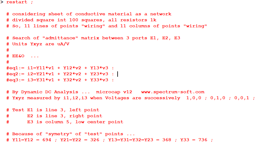
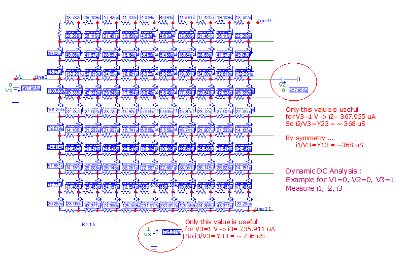
One can just consider this as a 3 ports "network".

Can be simulated with a "uniform" resistor network ... here, it is simplified.

enter image description here

Result matrix Y is obtained by DC Dynamic Analysis of this network.

enter image description here

So, it is not possible to "add" simply "Za", "Zb", or "Zc".

\$\endgroup\$
5
  • \$\begingroup\$ Very nice simulation. I was wondering why did you choose a 3-port network. In my experiment, I consider electrode E3 mainly as a ground and I usually apply voltages (I measure) between the different pairs of electrodes (between E1 and E3 for example). That's why I went for a 2-port network model. Do you think I can adapt your simulation, from 3-port to 2-port network, simply by assuming V3=0? I'm not sure what to do with i3 in that case. Especially that for a 2-port we would only work with V1,V2, i1, i2! \$\endgroup\$
    – Likely
    Commented Feb 8, 2022 at 23:18
  • \$\begingroup\$ For a 2-port network, simply disconnect E3. \$\endgroup\$
    – Antonio51
    Commented Feb 9, 2022 at 7:28
  • \$\begingroup\$ @Likely here something that can help you ... en.wikipedia.org/wiki/Van_der_Pauw_method \$\endgroup\$
    – Antonio51
    Commented Feb 12, 2022 at 19:10
  • \$\begingroup\$ @Likely microwaves101.com/encyclopedias/van-der-pauw-measurements aip.scitation.org/doi/am-pdf/10.1063/1.5001830 \$\endgroup\$
    – Antonio51
    Commented Feb 12, 2022 at 19:26
  • \$\begingroup\$ Thank you @Antonio51 :) \$\endgroup\$
    – Likely
    Commented Feb 14, 2022 at 16:37

Your Answer

By clicking “Post Your Answer”, you agree to our terms of service and acknowledge you have read our privacy policy.

Not the answer you're looking for? Browse other questions tagged or ask your own question.