3
\$\begingroup\$

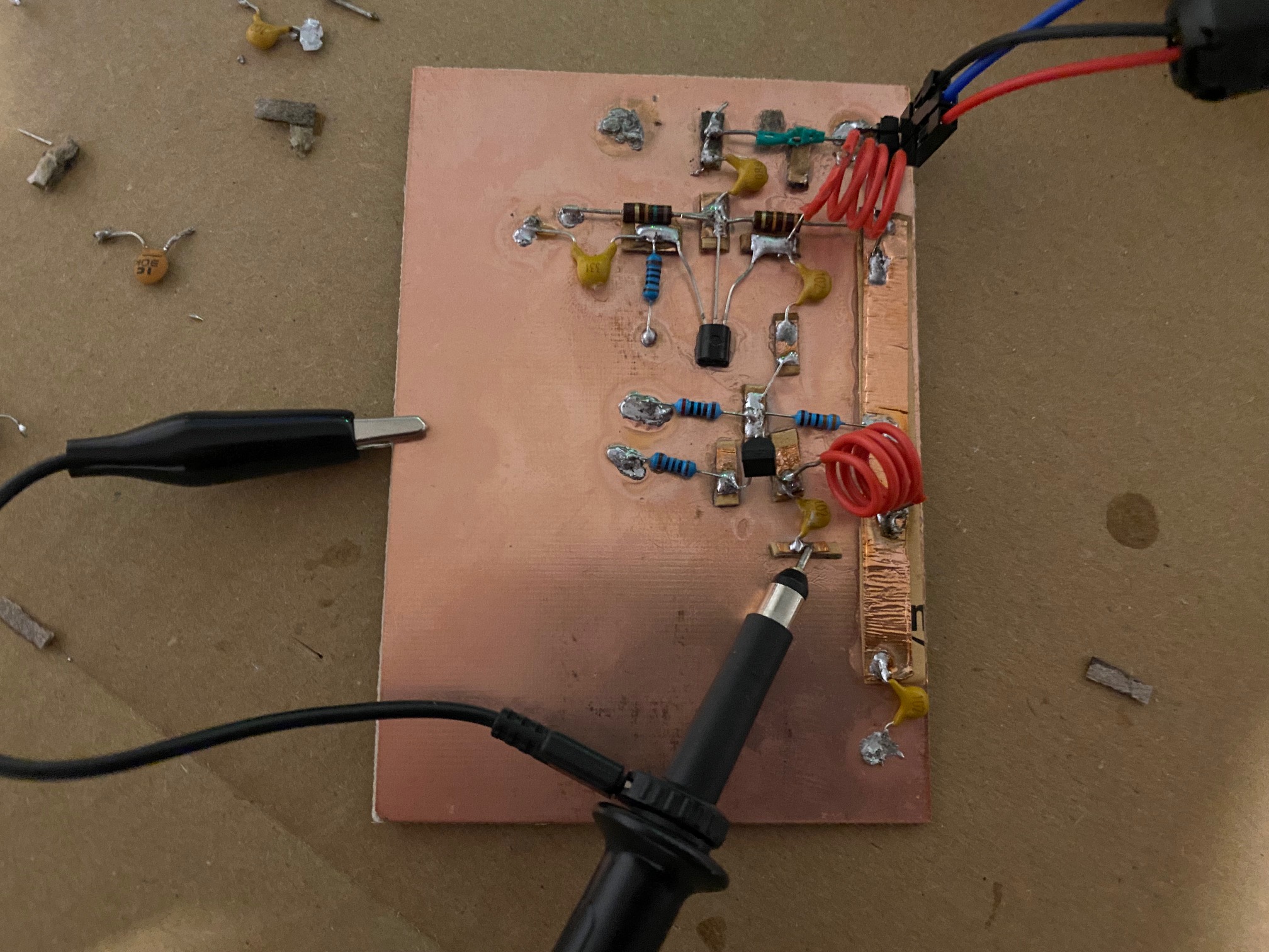
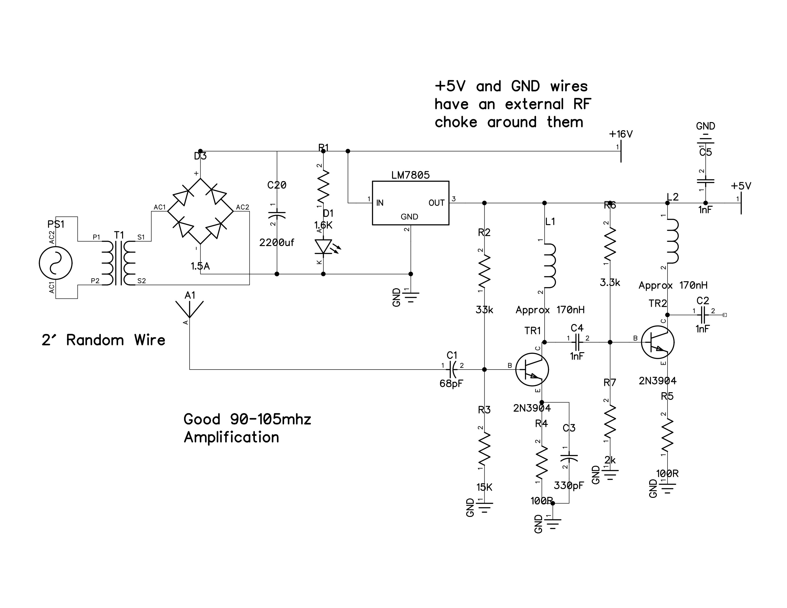
I am an RF enthusiast that wants to learn how to think like an engineer. I am trying to build a FM receiver that consists of a wideband FM amplifier and a slope detector. I have so far created an amplifier. It does seem to work but I would like to revise my thought process.

Assumptions that I have used for biasing:

  • In a CE amplifier, current through emitter resistor equals current through collector resistor.
  • Emitter resistor current is 100x the base current (Beta=100)
  • Biasing current should be at least 10x base current for stability.
  • Current flowing through both bias resistors is equal
  • Adding a emitter capacitor to ground increases gain via creating a lower resistance AC path to ground
  • Using an inductor instead of collector resistor lets you set DC bias and gain is proportional to frequency because of inductive impedance.

My arbitrary design ideas:

  • Emitter resistor should drop 1 volt, base voltage should be 1.6V
  • We have a 5V supply
  • datasheet for 2n3904 says B=100 if 10mA current flows through emitter. 1V/10mA=100 ohm emitter resistor.

Biasing TR1:

  • Emitter resistor current= 0.010A
  • Base current is 0.01A/100 = 0.0001A
  • Bias current should be 10*0.0001A=1mA
  • Larger bias resistor: 5V-1.6Vbase = 3.4V with 1mA through it, so 3.4K resistor.
  • Smaller bias resistor: 1.6Vbase/1mA = 1.6k resistor.
  • Add a bypass cap and simulate in LTSPICE for a good value, experiment with load inductor values.
  • Question: I grabbed wrong resistors, 34k and 16k which should violate stability rule of thumb. How is this stage still functioning?

Biasing TR2:

  • Base current is 10mA through emitter resistor/100 = 0.0001A base current; Biasing current should be 1mA, 10x larger than base current for stability.
  • Larger biasing resistor = 5V-1.6Vbase / 1mA = 3.4k (I have 3.3k on hand)
  • Smaller biasing resistor= 1.6V/1mA = 1.6k (I have 2k on hand)
  • Same inductor load because I know it works

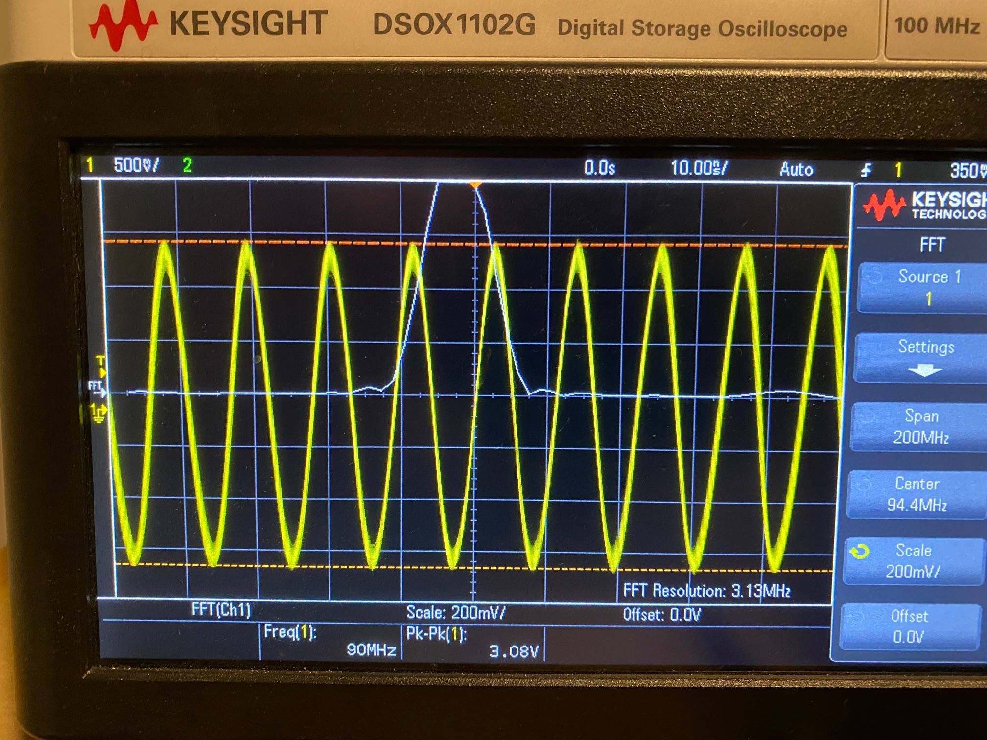
How can I think of amplifier design more formally? My only education on the topic is various youtube videos and internet tutorials on the subject. Thank you for your input. Schematic The Build Output Waveform
\$\endgroup\$
4
  • \$\begingroup\$ With a β of 100, the emitter current will be 101× the base current; β is the ratio of collector current to base current, and emitter current is the sum of the two. This does not actually matter, however, as β varies by quite a large amount for any given transistor, both between transistors of the same part number and for a single transistor at different temperatures. \$\endgroup\$
    – Hearth
    Commented Feb 5, 2022 at 6:09
  • \$\begingroup\$ I apply generally the rule Rb low (as R3) = 10 or 20x the emitter resistor (R4). R4 seems a bit too low, but it can be ok anyway (emitter current will be higher). One can now do a simulation "test" also to verify that DC analysis is ok. \$\endgroup\$
    – Antonio51
    Commented Feb 5, 2022 at 9:36
  • \$\begingroup\$ NB: no information about generator impedance and probe used (x1, x10)? \$\endgroup\$
    – Antonio51
    Commented Feb 5, 2022 at 9:59
  • \$\begingroup\$ Sorry, probe used was 10x \$\endgroup\$ Commented Feb 5, 2022 at 14:06

1 Answer 1

1
\$\begingroup\$

Here some results one should find. Good work ...

(Added parasitic capacitor on inductors, internal impedance of generator, and impedance "capacitance" of probe)

Also tested 0pF or 330pF at the emitter output stage.

enter image description here

And with some adjustment of inductors ...

enter image description here

\$\endgroup\$
3
  • \$\begingroup\$ Neat idea with simulating parasitics \$\endgroup\$ Commented Feb 5, 2022 at 14:07
  • \$\begingroup\$ We are in VHF ... So the parasitics are an important part of the system ... However, it is a good job. Need also "adapting" impedance at input to "antenna". An input "common base" stage would be useful (low input impedance). \$\endgroup\$
    – Antonio51
    Commented Feb 5, 2022 at 14:31
  • \$\begingroup\$ Makes sense. Thank you! \$\endgroup\$ Commented Feb 5, 2022 at 16:16

Your Answer

By clicking “Post Your Answer”, you agree to our terms of service and acknowledge you have read our privacy policy.

Not the answer you're looking for? Browse other questions tagged or ask your own question.