0
\$\begingroup\$

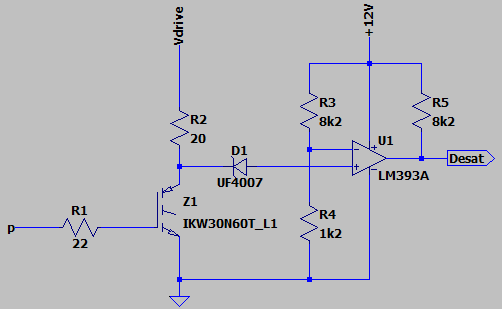
I am designing a circuit for driving a DC motor, and want to include overload protection, for that I found that detecting desaturation is a good option to detect high current flow.

enter image description here

I sketched the above circuit and it works in the simulation, but I learned the hard way that this doesn't mean it will work in real life. So, my questions are:

  • What kind of diode I should use for D1. I understand that it should be fast and rated for a high enough voltage. Is the UF4007 a good choice or is there a catch (maybe something related to it's capacitance?) I don't see yet?
  • How would I go about using that Desat signal for actually turning everything off? As soon as I turn the circuit off, the comparator's output is going low, so I can't simply attach it to the driver's (IRS2104) enable line. Sending that for the microcontroller to make a decision using code is a difficult choice, because since I'm using optocouplers (6n135), the time to go back and forth with that information is dangerously close to the rated 5us short circuit capability of the transistor.
\$\endgroup\$
2
  • \$\begingroup\$ Why not sidestep the whole problem by using a gate driver with built-in desat protection? \$\endgroup\$
    – Hearth
    Commented Feb 6, 2022 at 3:48
  • \$\begingroup\$ @Hearth The problem is this is an afterthought, the rest of the circuit is already tested and it would be time consuming and expensive to redesign it. Lesson for my next design, I guess. \$\endgroup\$
    – rubemnobre
    Commented Feb 6, 2022 at 3:50

1 Answer 1

4
\$\begingroup\$

You need a diode with sufficient reverse voltage capability to withstand the VCE of the IGBT. Note this could be greater than the supply voltage due to turn-off inductive spikes. You also need a low-current diode to minimize the capacitance. UF4007 may be a good starting point.

In your circuit, the junction capacitance of the diode will couple to the comparator when the IGBT turns off. You need protection on this circuit -- 1k in series with the diode and a 4.7 V zener from the + input to ground will work.

Lastly -- you don't have any specific pull-up source in your circuit for the comparator + input. Add a resistor (1k) from +12V also to the comparator + input.

The response time of your circuit will be limited by the various R.C time constants around. You may have to modify the resistor values to suit your specific case.

To detect desat, you have to a) wait for a short while after the IGBT is commanded on before reacting. Then if you do detect a desaturated, you have to latch that signal and use the latch turn off and hold off the IGBT. Depending on the situation, you may or may not allow it to turn back on at the next cycle -- generally this is not safe as the IGBT power dissipation could have been extremely high during the few us desat detection time.

\$\endgroup\$

Your Answer

By clicking “Post Your Answer”, you agree to our terms of service and acknowledge you have read our privacy policy.

Not the answer you're looking for? Browse other questions tagged or ask your own question.