0
\$\begingroup\$

I'm trying to measure the waveform on the drain of a low side MOSFET used as a switch for an LED with an oscilloscope.

I tried two different configurations with different components and power rail voltages. In both cases I see the square wave, but when the MOSFET is OFF the measured voltage is only 40-50% of the power rail voltage. If I replace the LED with a resistor, the waveform looks as it should.

With the second probe I measure also the IN-PWM signal and it looks perfect.

Why this behavior? Is there something related to the oscilloscope or probe that I don't understand? Should I measure it in a different way? I am using a HANMATEK DOS1102 scope with an x10 probe.
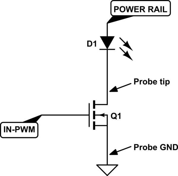
schematic

simulate this circuit – Schematic created using CircuitLab

\$\endgroup\$
1
  • \$\begingroup\$ If I replace the LED with a resistor, the waveform looks as it should. ... why do you conclude that the scope probe is somehow responsible? \$\endgroup\$
    – jsotola
    Commented Feb 7, 2022 at 9:42

2 Answers 2

2
\$\begingroup\$

You should have a series resistor for the LED. Hopefully you do and it's not shown.

If you add a resistor directly from the MOSFET drain to "power rail" you should get a waveform that is close to full swing at the drain.

There is nothing pulling up the MOSFET drain when the voltage across the LED drops to a couple volts or so (depending on LED color and construction), so even though the current drops to a very low level the capacitance of the MOSFET, LED and your probe will conspire to keep the voltage from rising very far. This is because the I-V curve of the LED is very nonlinear.

\$\endgroup\$
2
\$\begingroup\$

When not producing light, the LED has an electrical impedance that is very high (in the mega ohm region). This coincides with the MOSFET being turned off so, you get quite a high impedance node at the junction of drain and LED. That impedance is also affected by the impedance of the probe (also mega ohms) and forms a significant potential divider.

So, with the MOSFET off, the LED acting like (say) a 10 MΩ pull-up resistor and maybe the probe acting like a 10 MΩ pull-down resistor it means that the oscilloscope registers a voltage that is about half the supply rail of the circuit. You can prove this by putting a resistor of about 10 kΩ to 100 kΩ across the LED to drag that voltage up towards the positive supply rail. Don't forget the current limiting resistor for the LED also.

\$\endgroup\$

Your Answer

By clicking “Post Your Answer”, you agree to our terms of service and acknowledge you have read our privacy policy.

Not the answer you're looking for? Browse other questions tagged or ask your own question.