0
\$\begingroup\$

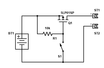
I have a fairly simple application:

enter image description here

Q1 is a P-Channel MOSFET. It had a flyback diode between drain and source (which is not illustrated here.)

Between ST1 and ST2 there is a 1k resistor to load the circuit by 5mA (BT provides 5V output.)

Unluckily, BT1 is providing negative voltage when it is turned off (-3V.)

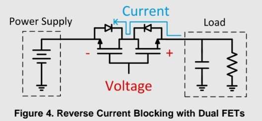
I came across with this circuit by TI:

enter image description here

I have some question about this, and I couldn't really find answers:

  1. What kind of MOSFETs are being used? (N or P channels?) I believe they should be P-channels, as their arrow is pointing out from them. However, in my diagram, the arrow is pointing towards the source while these are pointing towards the drain.
  2. Is this only a drawing difference? In other words, which one of these two would be my Q1? The left one or the right one? (I believe right one based on the flyback diode.)
  3. I can understand how this blocks reverse current when the gates are on GND. When they are opened up, I understand the right FET: current flows from source to drain (from left-to-right on the figure,) but what happens with the left FET? Why would current flow from drain to source in a P-FET?
\$\endgroup\$
4
  • 2
    \$\begingroup\$ It's not called a flyback diode; it's called the "bulk" diode and may or may-not act as a flyback diode in this application or that application. They are actually N channel devices and, to make them work, the gate drive voltage is taken higher than their sources (quite often with a photovoltaic opto generator). \$\endgroup\$
    – Andy aka
    Commented Feb 17, 2022 at 21:13
  • 1
    \$\begingroup\$ Maybe this answers your question: electronics.stackexchange.com/questions/566113/… \$\endgroup\$ Commented Feb 18, 2022 at 1:43
  • \$\begingroup\$ Addressing your edit: what's your load? Does adding a large resistor (e.g. 10k ohms) in parallel with the load make the observed voltage go away? \$\endgroup\$
    – nanofarad
    Commented Feb 18, 2022 at 17:59
  • \$\begingroup\$ Yes, it does. In case I tried with 330k, the voltage doesnt drop that much, and in that case, I can make the powerbank to turn back on (by applying a larger load of 1k parallel to 330k). But I am just about to test with the new circuit, so it might eliminate my problems :) \$\endgroup\$
    – Daniel
    Commented Feb 18, 2022 at 18:14

1 Answer 1

3
\$\begingroup\$

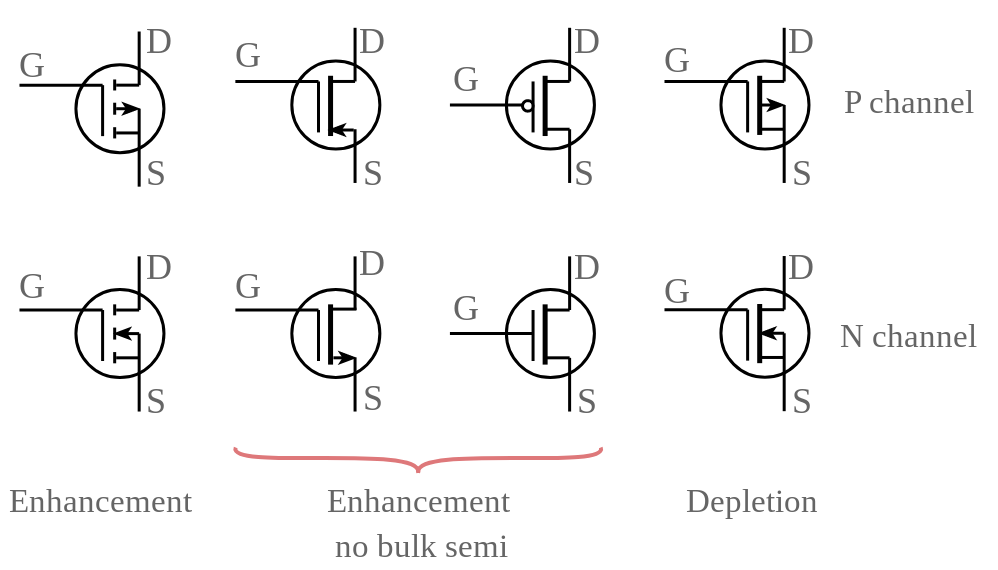
Those are nFETs with back to back drains. Unfortunately, the arrows are inconsistent when they point into the substrate vs out of the source:

enter image description here

Sourced from https://www.electronics-notes.com/articles/electronic_components/fet-field-effect-transistor/mosfet-metal-oxide-semiconductor-basics.php.

With that out of the way, this is really a different circuit algorther. In a reverse current situation, current is indeed flowing from source to drain through the body diode of the right FET, but it is stopped by the body diode of the left FET as long as the control voltage at the gate is low.

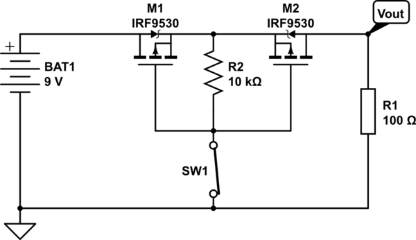
You may wish to consider a back-to-back pMOS pair instead:

schematic

simulate this circuit – Schematic created using CircuitLab

When BAT1 is providing forward voltage, your switch controls your back to back FETs -- closing the switch pulls the gate down to ground, turning both of them on and conducting right through their channels (there is not a diode drop from supply to load).

When BAT1 is outputting -3 V, then the gate is high relative to the leftmost source, so the left FET doesn't conduct. However, its body diode could be forward biased, which is why the right FET is necessary - its source is also pulled to ground by the load, preventing it from turning on. Its body diode is also oriented to not allow -3 V to be applied to the load.

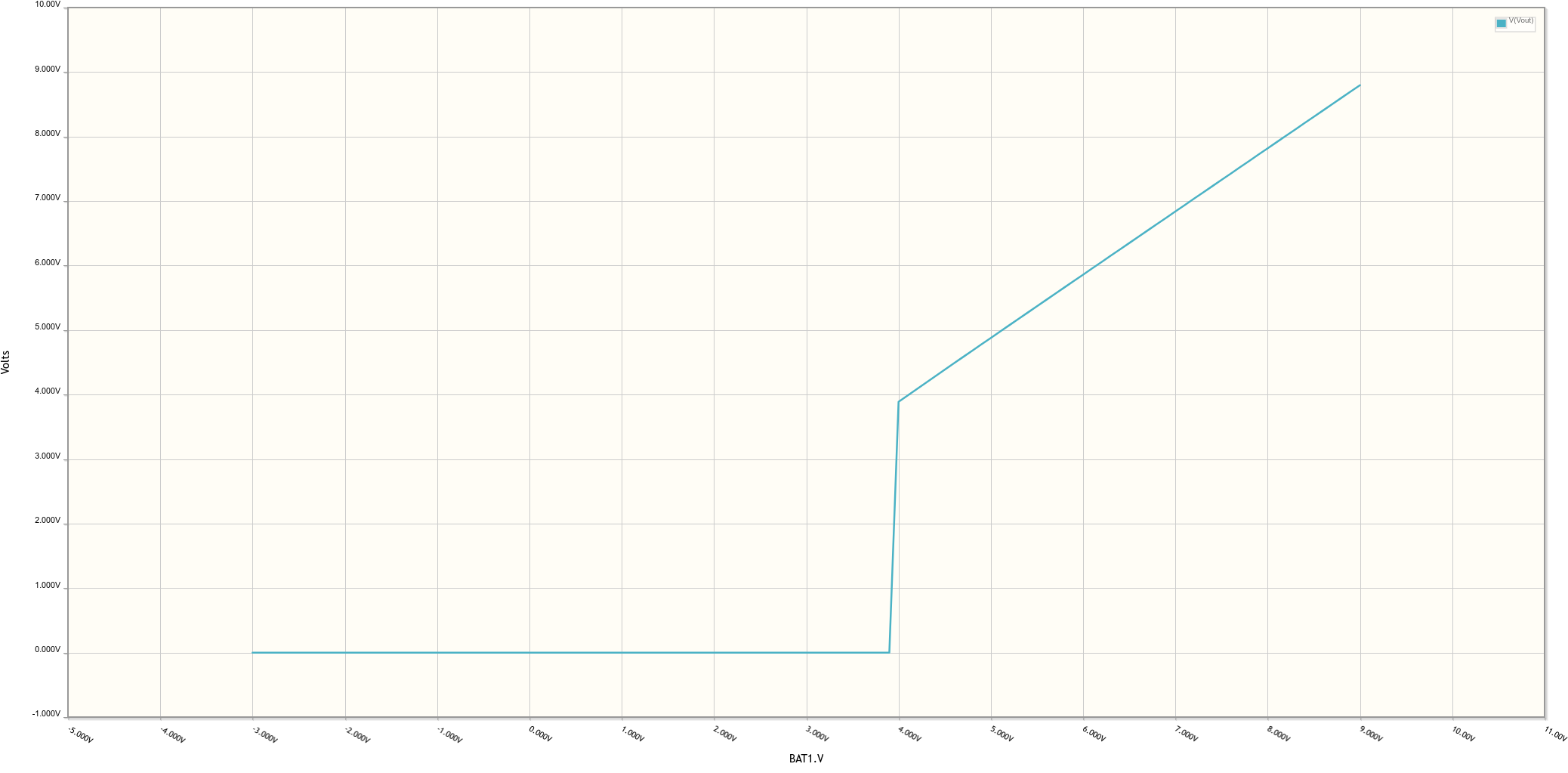
Here's the plot showing the output voltage as the battery voltage is swept from -3 V to 9 V with the switch closed:

enter image description here

With the switch open, the load voltage is always 0.

Note: The schematic was updated to incorporate a small change to the FETs (back to back sources rather than back to back drains and the resistor is moved) in order to make this circuit more robust in different scenarios such as back-feeding with multiple supplies.

\$\endgroup\$
6
  • \$\begingroup\$ Thank you. Very detailed, however can you a little bit more explain this part: ... conducting right through their channels (there is not a diode drop from supply to load): When they are ON, why the right one conducts through its channel and not on its body diode? \$\endgroup\$
    – Daniel
    Commented Feb 18, 2022 at 8:49
  • \$\begingroup\$ I think I found: both its channel and its diode conduct, but as the diode has a resistance of a magnitude of kilo if not mega-Ohms, and the channel itself has some milliOhms, vast majority of current will be transferred via the channel. Pretty sweet. :) \$\endgroup\$
    – Daniel
    Commented Feb 18, 2022 at 12:20
  • 1
    \$\begingroup\$ This works in this situation with a purely resistive load. If you're trying to completely eliminate conduction in either direction when off, I'd put the two sources face to face and run R2 from the gates to the sources. \$\endgroup\$ Commented Feb 18, 2022 at 16:55
  • 2
    \$\begingroup\$ Nah, easier to update this answer than add an almost identical one for this minor detail. I doubt your simulation would be much different unless you added a voltage source on the load side...this issue mainly comes in when trying to switch between sources seamlessly, so your alternate source doesn't get drained by a discharged primary. \$\endgroup\$ Commented Feb 18, 2022 at 17:03
  • 1
    \$\begingroup\$ Guys, thank you both. Note: earlier circuit didn't work out well, I believe due to the transients during the +5V -> -3V polarity change, but this one works rocksteady. There is not a single mV drop on the powerline now. \$\endgroup\$
    – Daniel
    Commented Feb 18, 2022 at 19:53

Your Answer

By clicking “Post Your Answer”, you agree to our terms of service and acknowledge you have read our privacy policy.

Not the answer you're looking for? Browse other questions tagged or ask your own question.