1
\$\begingroup\$

I have bought a DC-DC buck-boost converter which uses a potentiometer to set the desired output voltage. Now I want to 'remote control' this output voltage using a microcontroller.

Unfortunately, I have no circuit diagram of this small PCB. However, the datasheet of the LM2587 states, "When using the adjustable version, physically locate the programming resistors as near the regulator IC as possible, to keep the sensitive feedback wiring short."

Which ways do I have to make this possible?

For instance, how can I connect 1 of 4 selected fixed resistors to the converter, switched by any small galvanically-isolated device controlled by the MCU?

Relays would be too big. If I use, say, MOSFETs, I could create a ground loop, which I want to avoid because of above reasons.

For sure, I am not the first who would like to replace a fixed soldered potentiometer by a small circuit which allows Vout control by an MCU.

What are your suggestions to me?

Any advice is appreciated - thanks a lot in advance!

enter image description here

\$\endgroup\$
8
  • 3
    \$\begingroup\$ Without a circuit diagram, any replies/answers will be just be lists of possible methods for how the regulator might work, not a specific answer for the circuit you actually have. \$\endgroup\$
    – TonyM
    Commented Feb 23, 2022 at 21:50
  • \$\begingroup\$ What is the output Vmin,max adjustment range? \$\endgroup\$
    – D.A.S.
    Commented Feb 23, 2022 at 22:08
  • \$\begingroup\$ Most likely the circuit is not much more complex than what datasheet has. Basically you are looking to solve 2 issues. First is how to remove the trimpot and replace it with four selectable resistances of your liking. Then solve how to select between those resistance values. Too bad relays were discarded already. \$\endgroup\$
    – Justme
    Commented Feb 23, 2022 at 22:27
  • 1
    \$\begingroup\$ If you're going to control it with a uC you might look at digital pots. \$\endgroup\$
    – GodJihyo
    Commented Feb 23, 2022 at 22:33
  • 4
    \$\begingroup\$ If you have a DAC output , inject an offset voltage against the current thru 10k pot at max V using a calculated R to Vfb \$\endgroup\$
    – D.A.S.
    Commented Feb 23, 2022 at 22:44

3 Answers 3

6
\$\begingroup\$

Maxim Integrated makes a line of current-output DACs that are ideal for this purpose.

The DS4432 is a dual channel 8-bit current DAC that is I2C controlled. Datasheet: https://www.maximintegrated.com/en/products/analog/data-converters/digital-to-analog-converters/DS4432.html

Quite simply, current DACs used for voltage adjustment inject current into the feedback node, which adds or subtracts from the total current in the divider. Pull current out, voltage goes up; push current in, voltage goes down.

The big advantage of using a current DAC is that you don’t care about the Vref voltage. A side-benefit is some rejection of ground bounce: shifts between DAC ground and regulator ground will be cancelled by the current sink/source action. Also, it’s easy to set the adjustment range by setting the DAC current reference.

You can also do it with a PWM output. It’s trickier to design however, and injects some noise if it’s not well filtered.

If you only wish to select one of several fixed voltages, several FETs and resistors can do that under GPIO control.

Related: Changing output voltage of a buck converter by electronically swapping the feedback resistors

Uses a similar module: Buck converter limit upper voltage range

\$\endgroup\$
3
\$\begingroup\$

As Tony says, this is very easy to do. Maximum has an entire tutorial introducing the concept: https://www.maximintegrated.com/en/design/technical-documents/tutorials/8/818.html

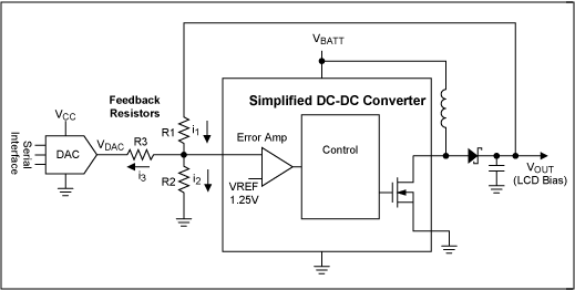
To briefly summarize, your DCDC converter is using that pot to form a voltage divider with the output voltage. The divided down voltage is then feed back to the converter, which tries to keep it at 1.205V, raising or lowering the output as needed to get that exact value. By adding one extra resistor (R3) to your pot (R1/R2) and a DAC hooked to your MCU, you can adjust that value however you want:

enter image description here

Intuitively, if VDAC is equal to 1.205, no current flows and the pot works as if no DAC was connected. If VDAC is less than 1.205 then current flows into the DAC through R1, resulting in a higher output voltage. If VDAC is greater than 1.205, current flows back into R2, resulting in a lower output voltage. Thus you can raise, lower or leave the voltage the same.

\$\endgroup\$
1
\$\begingroup\$

Thank you very much for all the comments and answers. I unfortunately did not have time to answer them up to now. So I start with the first comment and go through until the last one.

Dear TonyM, Yes it’s correct, I unfortunately do not have a circuit diagram, I would like to have one but I think I won’t get it. But that’s “fine” from my question point of view: I wanted to know which methods are “available” -- not that I implement e.g. MOSFETS but I didn’t think of a current DAC for instance.

Dear Tony Stewart EE75, I measured that I can set the output voltage between 3V and 15V and that’s fine for me. The datasheet writes something about switch voltage 60 or 65V, I do not care about this and therefore I even do not know exactly. Why you need this “input” to make an advice related to my question?

Dear Justme, I am not looking that you advise me in how to remove the trimpot. I was asking for concepts (methods) to solve my above question. E.g. an answer from “user1850479” is, to not remove the trimpot and nevertheless the job gets done (over an added current DAC).

Dear GodJihyo, as said, I am afraid to create a ground-loop, but yes that’s a possible idea.

Dear again Tony Stewart EE75, I think you mean something as “user1850479” suggested? That’s certainly a good idea which I really did not think of (over a DAC). However, I am not sure if you exactly meant the same, because you speak about “injecting an offset VOLTAGE”. If I understand you correctly I think this method will not work, because if the 10k poti is set to zero or to max, and I force a voltage over a DAC to this poti, one of those 2 guys will win. Or you mean this “using a calculated R to Vfb”, but then again, it’s a current, not a voltage which I force.

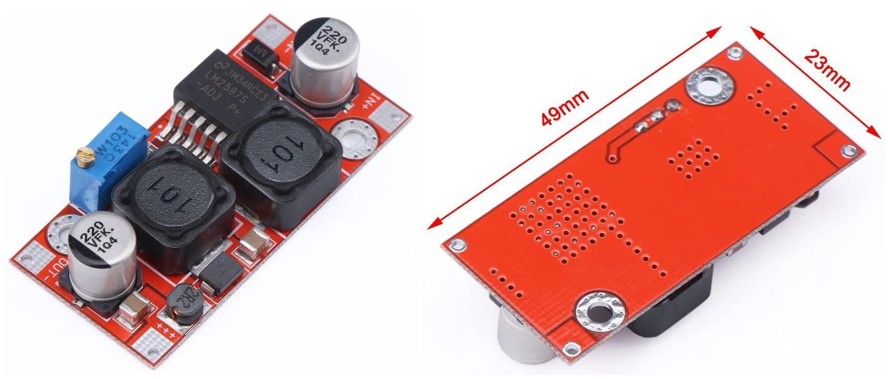
Dear Fred Cailloux, Your guess is wrong. I measured the PCB and the trimpot is connected with one side to the +OUT (so the POSITIVE output). To ground, a small fixed SMD resistor with 430 Ohms is connected. I also measured, that the 2 grounds ( -IN and -OUT ) are also connected together. As you can see from the backside of the PCB, 2 terminals of the trimpot are connected together. Anyway, as already said, I am afraid to create a ground loop if the output voltage selection is only done via MOSFETs. Basically I like the idea with optocouplers best (as already indicated inside my question) because I do not create a current loop and because the trimpot is “high-side-related” (to + Vout) , I don’t need to care about some things with the galvanically isolated optocoupler. But the problem with these devices is the high on-state resistance. Those I have searched have some 100 Ohms at least, which is too much. I would need an additional circuit/MOSFETs etc. Maybe there are ones available with lower Ron ?? Your other idea, just take the on-state-resistance of a FET directly as a poti and control the gate by a uC via a RC-RC low-pass-filter is not a good idea, if I have understood you correctly, because everything is strongly dependent on temperature. I prefer designs which are dependent on a ratio rather than designs depending on an absolute value.

Dear mkeith, A nice idea basically, which I also thought of, but, I unfortunately did not mention, this is 1st too slow and 2nd too big (at least as big as with relays).

Dear user1850479 and hacktastical, Thank you very much to both of you for showing the nice concept of introducing a current DAC! I am afraid of creating any ground loops with introducing a DAC but obviously, it is a common praxis which I was not aware of -- and therefore I would like to thank you! What I especially like is, that I can let the poti as it is and if the uC is not alive, the circuit will still be working as before. So, as this seems also a possible practical solution (since even Maxim presents this in an own paper), I now think that also just using some MOSFETs where I switch in- and out the suitable resistors could also practically be a good solution (I was afraid that I create a too large ground loop when using ANY not galvanically isolated device). To use the current DAC concept I would have to solder out the SMD resistor with 430 Ohms (and replace it with a higher ohmic one) since the DS4432 can handle at most 200 uA, but I think that will be no issue.

Again, thanks a lot for all the answers and I will think about all the options and decide which one will be best for me!

\$\endgroup\$
1
  • 3
    \$\begingroup\$ Note to future readers: This is confirmed as the desired answer to this question, by the question's author. A question's author can choose what is the conclusion to their question, so please don't flag this as "not an answer" etc. - it won't be deleted. Thanks. \$\endgroup\$
    – SamGibson
    Commented Feb 27, 2022 at 22:20

Your Answer

By clicking “Post Your Answer”, you agree to our terms of service and acknowledge you have read our privacy policy.

Not the answer you're looking for? Browse other questions tagged or ask your own question.