0
\$\begingroup\$

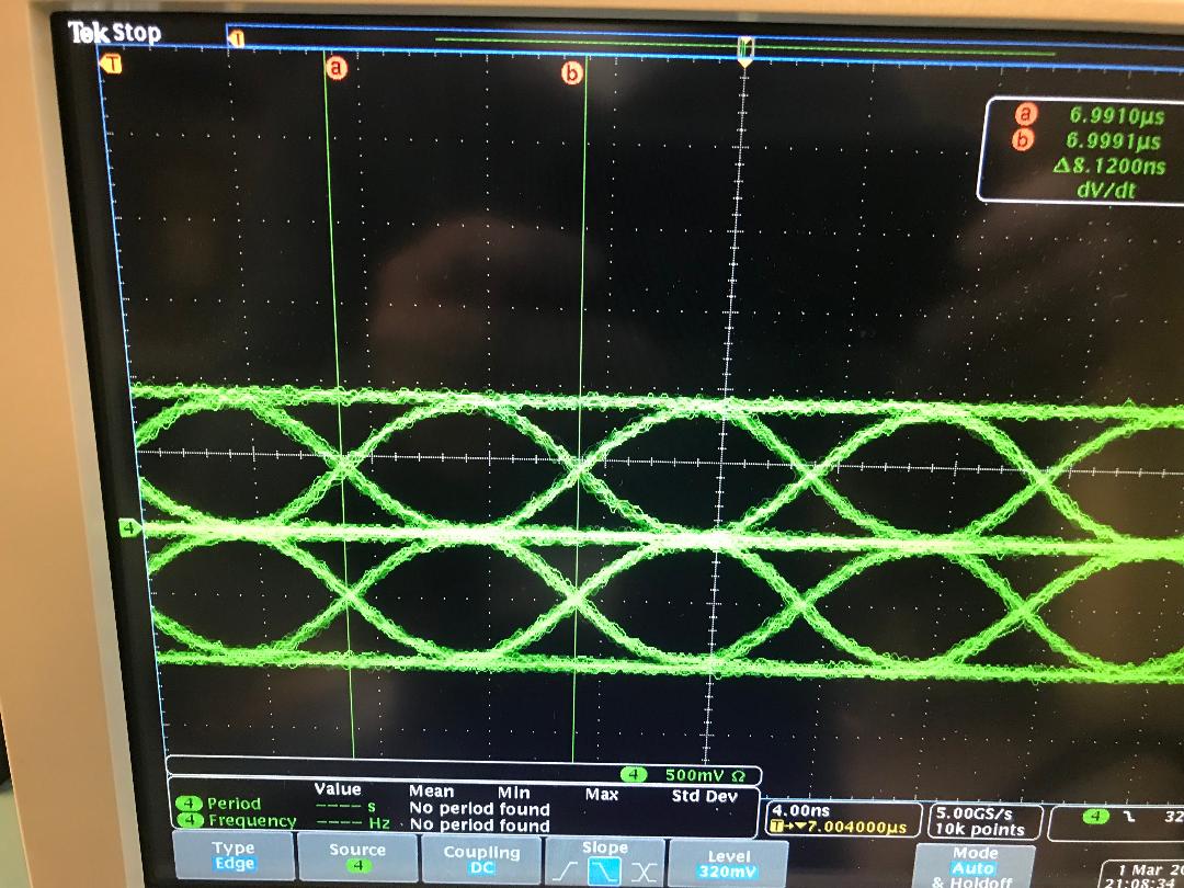
I measured the following waveform on a scope. It is a 100MBps Ethernet signal and I am measuring the TX+ and Tx- signals between the magnetics and RJ45 connector.

I see what looks like a double waveform (expected only 1), but do see this waveform show up sometimes when I google ethernet waveform

Couple of questions.

  1. is this double waveform ok?
  2. What is the best way to measure the eye (signal integrity) ensuring that this interface is solid?

Thanks!

Capture of Ethernet Waveform

\$\endgroup\$
3
  • \$\begingroup\$ Can you clarify a bit your setup? Perhaps this is clear to an ethernet expert (I am not) - my intuition tells me that you are using a differential probe connected between Tx+ and Tx-; is this correct? \$\endgroup\$ Commented Mar 1, 2022 at 15:37
  • \$\begingroup\$ download.tek.com/document/61W_17381_3.pdf \$\endgroup\$
    – Andy aka
    Commented Mar 1, 2022 at 15:41
  • \$\begingroup\$ @VladimirCravero. Yes it is a differential probe measurement \$\endgroup\$
    – Matty
    Commented Mar 1, 2022 at 15:54

1 Answer 1

5
\$\begingroup\$

This is the expected waveform for MLT-3 encoding as used on 100BASE-TX.

The full test suite is rather long and impractical to reproduce in this post.

You may compare with the eye mask specified in the standard as a first check given just the eye diagram. It's reproduced here among other places; certain test equipment will include a software feature that applies the mask directly on the screen aligned with the waveform.

\$\endgroup\$

Your Answer

By clicking “Post Your Answer”, you agree to our terms of service and acknowledge you have read our privacy policy.

Not the answer you're looking for? Browse other questions tagged or ask your own question.