0
\$\begingroup\$

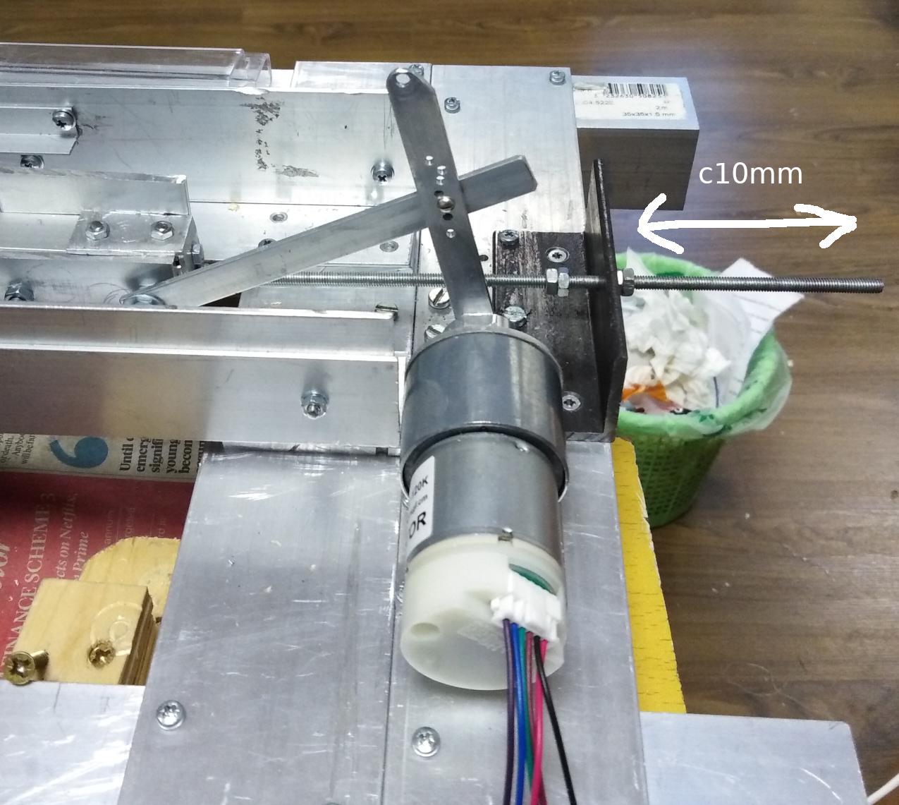
Firstly, this is not a homework etc question, but am trying to make a proof of concept for something. I have a mechanical force acting on a shaft (threaded bar) moving it in the direction indicated in the pic below:

enter image description here

Movement is roughly 10mm and force roughly 50kg/mm or 0.48 Nm. I an using this to drive a motor via a rudimentary crank. The movement is going from right to left in the pic above and is a one time thing, so results in about 10 to 20 degrees of rotation.

The first motors I tried were both brushed DC geared motors, 30:1 and 120:1, so this converted my small movements into a few turns of the actual motor. I also tried a stepper motor, I posted the results here.

My problem is, I'm not getting nearly the amount of power from the motor as I would like to see. I understand the power in watts is a factor of the time taken for the 10mm movement, and this is, in my setup, affected by the load, but by looking at the outputs on an oscilloscope I can view the duration of the 10mm movement.

The best result I got was 0.6W out for a theoretical mechanical input of nearly 5w (operation in roughly 100ms) which is ~10% efficiency. I think I'm loosing a lot in the gearbox, firstly having to accelerate it and the motor from a standstill (it's very hard to turn [get started] by hand with no load), then the frictional losses, and I think the fact I'm putting power in the "wrong way", into the output shaft is not helping.

Also, the speed of the motor is low, well below where it is designed to run as a motor.

The stepper motor seems to max out at ~0.6W even when driven by a mains drill @2,700 RPM - I salvaged it from a printer so no specs for it.

So my question is, what, if anything, might yield more power in my setup, where I can only turn the motor relatively slowly and for just a few turns at best. What will generate good power (in the 2-8 W range, so very small) at low speeds and has low frictional/inertial losses?

Maybe another stepper motor is worth a try? Or, I have not yet looked at BLDC. Would it be possible to make a linear generator of sorts?

UPDATE RE COMMENTS

3 March - Just to clarify some things from the comments so far (the first 4)

I think I confused things by saying I drove the stepper with a drill. This was just to test the stepper in isolation - I am not trying to generate electricity by using a motor to turn a generator.

Yes, there is a force acting on the rod. I should have used the word work in my figures. If you allow me to be a little lax with terms for a second, there is 5gk pulling on the rod and it moved 10 mm which is 50kg/mm of work, or 0.05kg/m *9.8 =0.49Nm of work. I measured this with a load cell.

If I can summarise my question, the DC motors I have are designed to run at roughly 4,500 rpm, even with the gearbox I'm not getting anywhere near that speed, and I believe the gearbox is causing huge losses. I have no specs on the stepper but it seems to top out at 0.6W regardless of how fast I run it.

So, what might be my best bet to generate 2W to 8W while running at a low speed (< 1,000 RPM)

\$\endgroup\$
10
  • 1
    \$\begingroup\$ You have electricity going in at one end and 10% of that electrical power coming out of the other end - why not bypass the whole thing with wires. I'm saying this because I know you are trying to achieve something but, it's really unclear what you are trying to do and it might help folk get a better picture if they are told. Do not use the words perpetual motion in case you were thinking you might. \$\endgroup\$
    – Andy aka
    Commented Mar 2, 2022 at 17:58
  • \$\begingroup\$ I don't quite understand the "Movement is roughly 10mm and force roughly 50kg/mm or 0.48 Nm". Do you have an external force pulling the rod? Can you have gears and a flywheel? \$\endgroup\$
    – Ralph
    Commented Mar 2, 2022 at 18:03
  • 1
    \$\begingroup\$ What linear force does the thing attached to the 'threaded bar' (not the lever) produce? How do you know that it is 0.48 Nm on the motor shaft? What does '50kg/mm' mean? \$\endgroup\$ Commented Mar 3, 2022 at 3:12
  • \$\begingroup\$ Your force would be in newtons, not newton meters. I'm guessing you made a mistake with your energy calculation. I also wouldn't expect an efficiency much higher than 10% for a crude setup such as this. Even if everything was perfectly engineered you might only see 50%. \$\endgroup\$
    – Drew
    Commented Mar 3, 2022 at 3:23
  • \$\begingroup\$ @Andyaka Thanks, but I just rant the stepper with a drill to test it in isolation. I updated the question. And no not perpetual motion :) \$\endgroup\$
    – KevInSol
    Commented Mar 3, 2022 at 12:55

2 Answers 2

1
\$\begingroup\$

there is 5gk pulling on the rod and it moved 10 mm which is 50kg/mm of work, or 0.05kg/m *9.8 =0.49Nm of work. I measured this with a load cell...

The best result I got was 0.6W out for a theoretical mechanical input of nearly 5w (operation in roughly 100ms) which is ~10% efficiency.

You are putting 5 watts of mechanical power into the mechanism, but not all of it is getting to the motor. Your lever arm has a high angle which is bound to cause losses due to the sideways force. You should offset the motor so the lever is as close as possible (on average) to horizontal.

I think I'm loosing a lot in the gearbox, firstly having to accelerate it and the motor from a standstill (it's very hard to turn [get started] by hand with no load),

Yes. Your gearbox ratio is too high, and it has a lot of gear stages with each one adding to the loss. With your lever setup you could probably use a gearbox with about 1/4 the ratio (and motor arm 1/4 the length) and still have an acceptably small angle of rotation.

Another problem is inertia of the motor and gearbox which stores kinetic energy as it winds up, some of which is lost when the mechanism hits its stops and/or changes direction.

Also, the speed of the motor is low, well below where it is designed to run as a motor.

This moves the best efficiency point to lower power, where mechanical friction losses (brush, bearing, gearbox, coupling mechanism) become more important than electrical losses. That's not necessarily a bad thing, but it does mean you need to keep mechanical friction losses low. On the upside the motor will put out higher voltage than a lower voltage motor would at the same speed, which could be important for efficiently utilizing the power produced.

I have no specs on the stepper but it seems to top out at 0.6W regardless of how fast I run it...

Maybe another stepper motor is worth a try? Or, I have not yet looked at BLDC. Would it be possible to make a linear generator of sorts?

Stepper motors generally have low efficiency. 'Small' brushed DC motors are typically 50-60% efficient at optimum loading. A coreless motor may be better because they have low friction and inertia. BLDC have the advantage of no commutator loss and potentially higher efficiency, but need a rectifier to generate DC.

However for your small travel a 'linear' motor might be the best option (if you don't mind building one).

So, what might be my best bet to generate 2W to 8W while running at a low speed (< 1,000 RPM)
You won't get 8 watts out of 5 watts, so I presume you want to make a unit that accepts higher power. 2 watts from 5 watts is 40% efficiency, which should be achievable with a good quality brushed or brushless motor if the mechanism is optimized for it.

At < 1,000 rpm you need a high quality gearbox and/or a motor that is designed to run efficiently at low rpm, and with only 100 ms operating time you also want low inertia (or some way to recover the kinetic energy when the mechanism stops). With 10 mm travel a 'linear' generator could be more efficient due to having fewer parts and more direct power production, but might have to be custom made.

You haven't told us the purpose of this device or what is applying the force. You talk about 'watts' but this doesn't make much sense if only a single stroke is involved. If that is all you want (2 W for 100 ms) then you might want to consider other ways of getting it.

\$\endgroup\$
8
  • \$\begingroup\$ Thank you! Re your comment about the lever, I have tried several levers and attachments, most of which the lever is shorter and everything more in line with the threaded bar. This was just an early pic (rig is in a somewhat dismantled state now so unable to take pic of current setup). About the gearbox, I know it's an issue, and indeed tot 30:1 outperformed the 120:1 \$\endgroup\$
    – KevInSol
    Commented Mar 4, 2022 at 17:17
  • \$\begingroup\$ "You won't get 8 watts out of 5 watts," - I understand that. What I mean, and sorry for the confusion, is that the rig can be configured to generate more mechanical power. I just went with the mid point 5W figures to keep things simple for the posting. \$\endgroup\$
    – KevInSol
    Commented Mar 4, 2022 at 17:36
  • \$\begingroup\$ You are the second to suggest a BLDC and linear. I'll look into them. Re building my own linear, would that be difficult? \$\endgroup\$
    – KevInSol
    Commented Mar 4, 2022 at 17:43
  • \$\begingroup\$ A lot more difficult than using an off-the-shelf motor, but potentially a lot more efficient if you build it right. You have to decide whether it's worth the effort. \$\endgroup\$ Commented Mar 4, 2022 at 20:29
  • 1
    \$\begingroup\$ The lower the Kv the more voltage it will produce per rpm, so if you want more voltage a lower Kv is better. However lower Kv implies more turns which means higher resistance and lower power output at peak efficiency. The best motor will have a low Kv and a low rated operating voltage (and high rated power output at high efficiency). \$\endgroup\$ Commented Mar 8, 2022 at 19:24
2
\$\begingroup\$

trying to make a proof of concept

You have some evidence that the concept is difficult and inefficient at the scale implemented. It would probably work better at a larger scale.

rudimentary crank

"rudimentary" is part of the problem

I think I'm loosing a lot in the gearbox

That is to be expected even with the best (most expensive) gearbox. Efficiency is inversely proportional to speed reduction.

So my question is, what, if anything, might yield more power in my setup, where I can only turn the motor relatively slowly and for just a few turns at best.

The best alternative is likely to be a 3-phase, permanent-magnet, synchronous motor with as many poles as possible. Many poles means lowest speed for a given fundamental frequency. A brushless-dc motor without the electronic controller would probably be second best.

An arrangement using a solenoid coil with a permanent-magnet plunger might be worth investigating.

\$\endgroup\$
2
  • \$\begingroup\$ Thanks for the input, and my gut says yes it may work better on a bigger scale. I'm just looking for some reassurance before committing to that. I had a look at synchronous motors, the costs seem to rias very quickly. I found one that stated 5W out for 29W in - is this typical, and if so, looks to be worse than what I'm getting so far? Good idea about the solenoid. Most, as far as I can see, have an iron/steel plunger, but will look for a magnet one. \$\endgroup\$
    – KevInSol
    Commented Mar 4, 2022 at 17:11
  • 1
    \$\begingroup\$ You won't find a solenoid with a magnet plunger, but it may not be too difficult to make a magnetic plunger to replace a steel one. I don't know much about tiny motor efficiency, but I am surprised at 5W out for 29W in. I would have expected something much better than that. \$\endgroup\$
    – user80875
    Commented Mar 4, 2022 at 20:01

Your Answer

By clicking “Post Your Answer”, you agree to our terms of service and acknowledge you have read our privacy policy.

Not the answer you're looking for? Browse other questions tagged or ask your own question.