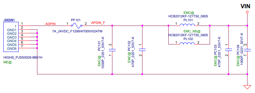
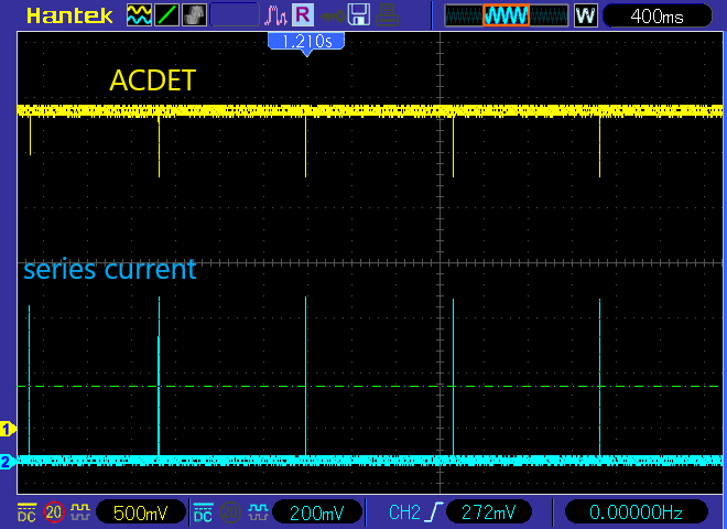
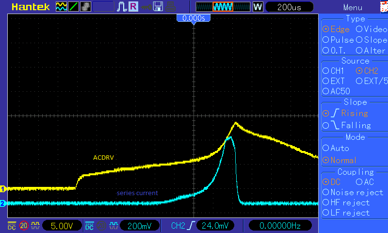
Intro how it happened:
I had cleaned my laptop from dust and reapplied the thermal paste. After this i have reassembled the device than it did not turned on. Then i took it apart connected the fan and it worked even POWER led was lit. Skipping the part when i constantly reassembled the laptop then find out it's not working so i started to remove the cables from the motherboard ( keyboard, fingerprint scanner etc ... )
Now i am at the situation where it wont turn on at all. I can hear a clicking sound every 2-3 seconds. Here is where i would like to ask for your help.
Measurements on motherboard:
Maybe the laptop adapter is wrong: I have connected my lab bench psu and it won't work with that as well.
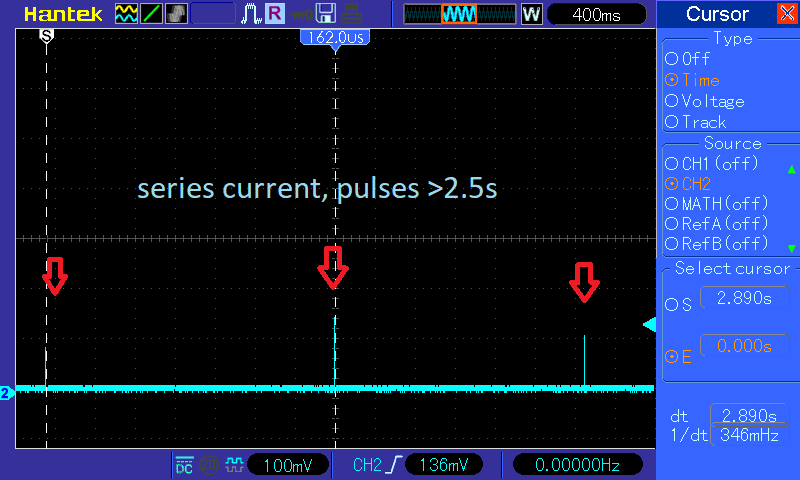
Clicking noise---> let me see what is the ingoing current looks like
MOBO powered from DCIN, it's connector. Series current, 100mV/A, 568mV corresponds to around 5.7A
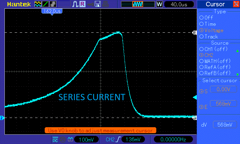
From bird-eye view the current form looks like the following:
[
- Maybe there is a shorted capacitor. I have checked a couple of points on the circuit. Mainly it's input stage but nothing i have found. Also thinking of a short the component which malfunctions might heat up. With my thermal camera i didn't find anything hotter then +40°C (voltage rails are present so the DC/DC converters are doing something)
Here is where VIN goes,high side swtiching mosfets:
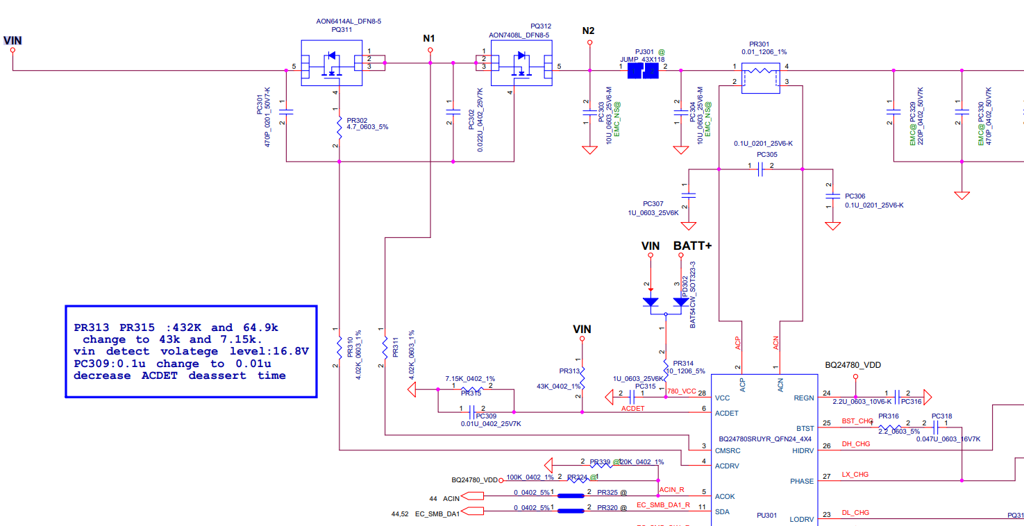
Voltage injection: I started injecting 5V after the switching mosfets(PQ311,PQ312) with current limit to see if i found the short. There was no high current so
-I injected 18.5V to PJ301 (basically N2) and the MOBO's POWER LED was lit.
-Injected 18.5V on N1 and the power led was lit
Voltage injected on either N1 or N2 produces the following current waveform:
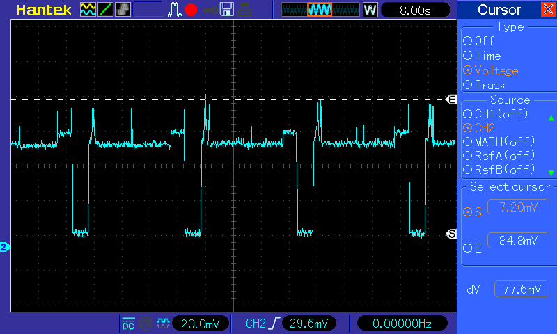 When the led is blinking the current is at on the wave's top part(at the level of the menu text MATH(OFF)). When the current is at "cursor S" the led is OFF constantly. To me without thinking much about it it looks like the MOBO is working and managing itself.
-Injected 18.5V on VIN then MOBO is not working but shorting PQ311(source and drain together) "does the trick" and MOBO works.
I have replaced PQ311 as came to the conclusion i had no better idea at that point. Changing PQ311 has not solved the problem, i was feeling it won't but anyway proceeded with chaning. I tested components connected to VIN if they are shorted or something but not found any suspicious.
I put additional measurements i made on the circuitry that might help you:
Voltage injected on DCIN while measuring voltage on ACDET point during inrush current. (LED is not working)
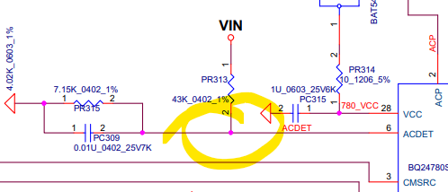
Bird-eye view
Voltage injected on DCIN while measuring voltage on ACDRV point during inrush current. (LED is not working)
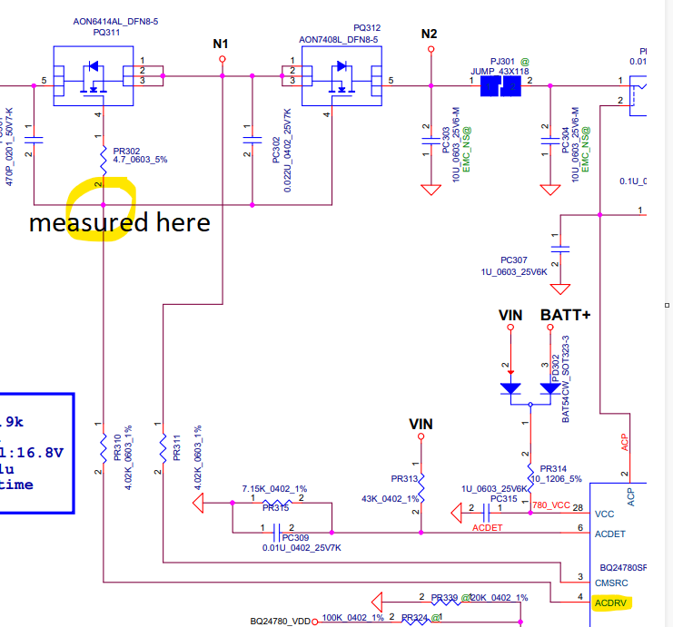
Voltage injected on N1. LED is working
During this i measured 25.4V on ACDRV with a DMM
At this point i would like to ask you for your thoughts and help.
Follow-up:
2022-03-15:I was checking the capacitors and power rails if there is a short to ground. I was doing as Ilya suggested, not looking at the schematic. I find only low impedances on the rails which connect to the CPU or GPU, around 10-15 Ohms. Also checked every voltage on the following schematic and they were all present
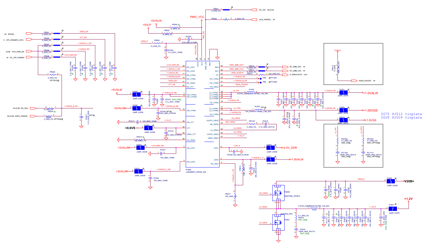 While doing this the board came alive.
So thinking a bit and left with no other option i begin to clean the board once again. Clean the applied heat paste as well ,from CPU and GPU. I looked it up before and this thermal paste is a non-conductive type so in theory it can't cause short right(thermal paste link)?! Also saw some really small amount at two points on the pcb where there was solder mask underneath it. I cleaned these as well(the thermal paste got transfered to these points during the analysis measurements). I am giving this cleaning a 50-50 chance as now i have no better option. I will assemble together the PC when i will have time, altough i have connected the FAN and it worked. I switched on and off of the supply to see if it will power up. Done it more than 15 times and it have not had any problem.
2022-05-10:Cleaning did not solve the issue. Altough i have some new information.
- I have started going brute force. Desoldered all the tantalum capacitors and electrolytic if they might cause the sort. This has not solved the issue.
- Tested power rails by injecting 1.2V to see if there is a short. This has not solved the issue.
- I have replaced BQ24780SRUYR and the 10mOhm shunt. This has not solved the issue.
Now i have found some interesting stuff. If i put a wire like so:
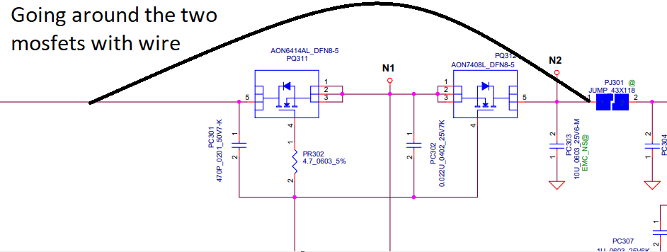 device starts up, LED lights up. Then while the device is still powered and working I remove the wire and the device kept on going. To me this means there is some transient during startup which causes the problem and triggers some protection.

