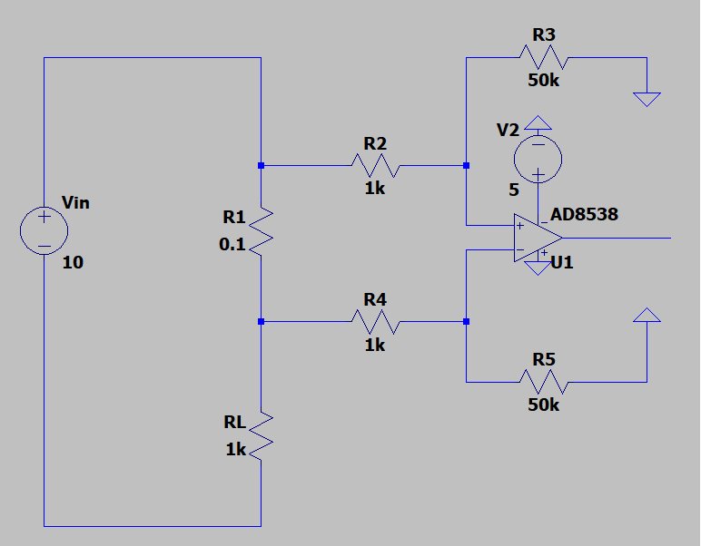
For this application, a high-side current sense amp chip like this one or MAX4376 would be a nice choice.
Unlike a normal opamp, these allow an input common mode range above their power supply voltage, so they will work. The opamp in your schematic can't handle input voltages above its supply voltage, so it won't work.
In addition these chips include the precision resistors, and they have much better CMRR than what you can achieve with 1% resistors.
The schematic on the first page of the datasheet looks exactly like yours, but don't be fooled by that... they don't give details about the internal schematic, but the high input current gives away the trick: the input stage is most likely powered from the input pins themselves, which is why it can work above the supply voltage of the chip. This is okay in a current sense application, because you're measuring voltage on a very low resistance tied to a power supply, so a bit of input current drawn from that won't hurt accuracy. These chips would be terrible as general purpose opamps because of this, though. But they're really good as a high-side current sense amp.
To pick one, first check if you need current sensing in one direction or both. Some only do one direction, and will output 0V when there is no current... others will do both directions, but since they're single supply chips and can't output a negative voltage, zero current will be an output voltage like VCC/2. Others have a REF pin so you can give it a reference voltage, and it will output referenced to that.
Then check offset, bandwidth, noise... check the "in stock" box, burn a candle and sacrifice a chicken (maybe two these days) and sort by price.

