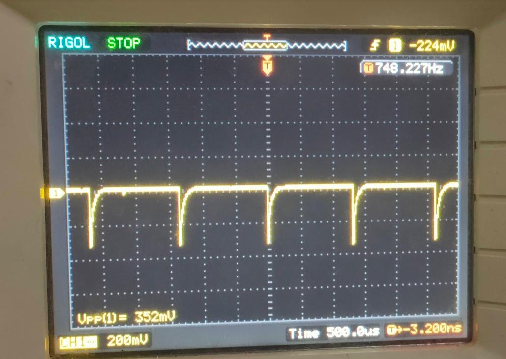
I am using PIC32MZ microcontroller for ADC input scanning. I have 10 inputs. Some of them are resistor dividers, others feed with opamps. I get some kind of voltage drop in every sense input. The timing of this drop is different. Can ADC input scan switching cause this much voltage drop? All my measures are correct. I have no problem with that but this peak effects other parts of the circuitry. When i remove a pin from input scanning peak removes. How can i remove this peak while doing input scanning?
-
2\$\begingroup\$ Every time the ADC samples, the pin will draw some current to charge the internal capacitor of the sample-and-hold circuit. What series resistance do you have on the inputs? \$\endgroup\$– Klas-KennyCommented Mar 15, 2022 at 21:02
-
3\$\begingroup\$ 1M-200k is crazily much. Even if you have a pair of picofarads of input capacitance, you have a whole RC circuit with massive resistor. Try making op amp buffer (voltage follower) and feeding it directly into input pin without any resistor and see what happens \$\endgroup\$– IlyaCommented Mar 15, 2022 at 21:51
-
1\$\begingroup\$ What happens if you put a 10nF cap on the adc input? Assuming your inputs are low frequency? \$\endgroup\$– KartmanCommented Mar 15, 2022 at 21:58
-
1\$\begingroup\$ Just add a small capacitor at the input of the MCU to supply the charge needed for the input sampling capacitor. Maybe 1000pF. \$\endgroup\$– Kevin WhiteCommented Mar 15, 2022 at 22:00
-
1\$\begingroup\$ Thanks everyone adding a small cap solves problem everywhere with resistor divider and opamp output. I guess instant switching of adc scan creates current rush to the sample cap. And adding a cap to the input solves problem. Thanks. \$\endgroup\$– Ahmet AtcıCommented Mar 15, 2022 at 22:49
1 Answer
That's entirely expected: A/D sampling on those MCUs connects a small capacitor to the input pin. This capacitor is usually discharged, and the switch+capacitor circuit are wideband and slew fast, in tens or at most hundreds of nanoseconds. They are nasty loads to deal with, and if you ignore the problem, you get nonlinearities and/or noise.
Whatever you use to drive this pin must be able to cope with such fast transients. If you don't have a fast op-amp driving the input, you'll need a fairly large decoupling capacitor, say 1uF at the input pin, and 50-100 Ohm isolation resistor at the output of the op-amp. If your load inherently has source impedance in the 50-100Ohm range, you won't need the isolation resistor. If the load's impedance is higher, you'll definitely need an op-amp voltage follower to isolate the ADC load from the source.
If, on the other hand, your op-amp is suitably fast, say >10MHz GBW and >40V/us slew rate, then you can use a much smaller decoupling capacitor - 0.5-2nF, and also a smaller isolation resistor - say 25-50 Ohm.
In my experience, rail-to-rail output op-amps running at small gains (<2.5), with GBW > 10MHz and slew rate >40V/us are typically suitable for "slow" ADCs that sample 100kS/s or slower, as long as they settle to your desired resolution well under 1us. The actual requirement is the aperture or "sampling window" of the A/D converter. You'll need even faster parts for faster sampling ADCs or higher resolution than 14-16 bits.

