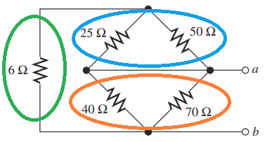
"It is difficult for me to spot what is in series and in parallel."
That's your problem. You need practice visualizing series and parallel connections. Your trouble is pattern recognition and we need to give you some advice about it.
All of the previous answers gave you the same advice: redraw the circuit. That's good advice! But in the case of resistive networks, you need to redraw it with the goal of making the patterns obvious. So, here's some more advice:
If you haven't been introduced to it yet, allow me to introduce you to a basic engineering acronym:1 KISS! It stands for Keep it Simple, Stupid! That's not meant to be rude! It's meant to remind us2 that simple is a really good goal.
KISS! Whenever you see a line like the (a) line, where there are multiple connections that are spread out, but it's really all the same electrical point or connection, that should warn you that the picture has complexity that electrically doesn't exist. Learn to identify common nodes that have been spread out.
This is an important skill. Paper schematics are becoming a thing of the past, but they can teach you a thing or two! I have the schematic of an old electro-magnetic pinball machine that commonly uses straight lines that are (I kid you not...) several feet long. Along those lines hundreds of components are connected and they quite literally represent wires running all over the place connecting those components in the machine. You need to learn to recognize these common nodes for what they are: one electrically equivalent point.
KISS! While in real life you might find a circuit that's physically laid out with diagonal components, it'll happen a lot less than you might think. So your next task is to straighten everything out. This will help you see the patterns.
KISS! Look for a simple resistor pair (just two resistors) that is in a basic-series or basic-parallel configuration. Reduce the pair to a single resistor.
Examining your fist example, the 6Ω resistor doesn't appear to be paired with just one of anything, so we ignore it. If we redraw the diamond circuit so the symbols are all vertical rather than diagonal, you should be able to recognize the two parallel pairs: the 25Ω and 50Ω pair, and the 40Ω and 70Ω pair. Remember: Look for simple pairs.3
- KISS! Reduce each pair to a single resistor, then re-examine the new schematic. In other words, repeat step #4 until all the basic pairs are gone.
After reducing the two parallel pairs, we're left with three resistors. Remember step #4! We're only looking for pairs! The simplified 40Ω/70Ω resistor is not paired with anything so we ignore it for now. On the other hand, the 6Ω resistor is in series with the combined 25Ω/50Ω resistor, so we reduce that pair.
What's left are two resistors, the 6Ω/25Ω/50Ω combined resistor and the 40Ω/70Ω combined resistor, and they're in parallel. So we invoke step #4 again and reduce them to a single resistance.
What's left over will be one of two things: either (a) it will be a single resistor or (b) what's left has no series or parallel combinations. But (b) is something to discuss in a later question.
Remember, the goal of my answer is to help you to learn how to more easily recognize basic-series and basic-parallel resistor pairs in a large(ish) circuit — like learning to see individual trees in a forest. Learn that, and no pretty picture will ever confuse you.
1 Engineering is filled with quality acronyms and mnemonics like KISS! But they're not always... well... (*ahem*)... politically or socially correct. This is one of the better ones. How I was taught to remember the resistor color codes in high school would probably offend the socks off people today. But I've gotta admit... it's memorable....
2 And believe me, we all need the reminder from time to time. The phrase "over-engineered" exists for a reason.
3 If you don't have trouble recognizing basic-series and basic-parallel pairs, skip this footnote. If, on the other hand, you're having trouble remembering what a basic-series or basic-parallel pair looks like, open this page to remind yourself.


