3
\$\begingroup\$

I have built an integrator to act as a 5V 30Hz square wave to triangle wave converter.

enter image description here

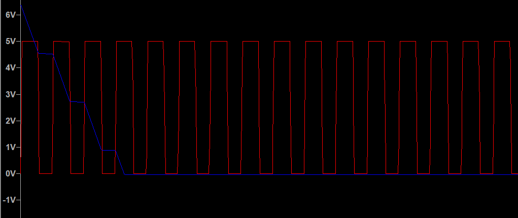
My output currently looks like this.

enter image description here

I am unsure why. The value of the triangle wave amplitude, according to one of this posts' answer, should be 0.833, which is within the amplitude of the op-amp. There is probably something very fundamental that I am missing. If any more information is needed, please let me know.

\$\endgroup\$
5
  • \$\begingroup\$ Have you tried different resistor (10k), capacitor (20pF)? Also, try placing some high-resistance load on the output (100k). In general, try fiddling with it a little and see what affects what \$\endgroup\$
    – Ilya
    Commented Mar 28, 2022 at 12:27
  • \$\begingroup\$ Do you want to convert a "square" wave or a "Pulse"? As shown the circuit shows pulse 0 - 5. \$\endgroup\$
    – Nedd
    Commented Mar 28, 2022 at 12:30
  • \$\begingroup\$ @Ilya I have modified the loads for 10 minutes. The output is always near-identical. \$\endgroup\$ Commented Mar 28, 2022 at 12:31
  • \$\begingroup\$ @Nedd It is a square wave, just that LTSpice calls everything a pulse wave. \$\endgroup\$ Commented Mar 28, 2022 at 12:32
  • 1
    \$\begingroup\$ To be sure give the "Pulse" a DC offset to make a true bipolar signal with the mid point at 1/2 V+. \$\endgroup\$
    – Nedd
    Commented Mar 28, 2022 at 12:33

1 Answer 1

6
\$\begingroup\$

It won't work without a high value feedback resistor like this: -

enter image description here

An op-amp integrator can never approach an ideal integrator because of the need to stabilize the DC output to somewhere near mid-rail and, that is what the resistor will do. Given that you have a 100 kΩ input resistor, you'll need something like 10 MΩ or greater as your feedback resistor.

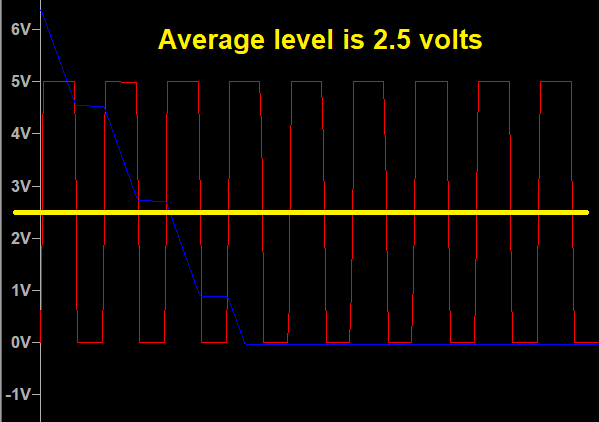
The next problem is your input signal DC offset: -
enter image description here

An integrator does what it says on the tin - it will integrate the DC level of your signal and, it sounds like you don't want this to happen. So, you have to remove that DC level either with an offset adjustment circuit or a high pass filter. Maybe try this: -

enter image description here

Here's my simulation and note the time it takes to settle down to a reasonable DC mid-rail value. Note that I've run the AD822 from a +5 volt rail and not a +15 volt rail to make things clearer: -

enter image description here

enter image description here

If you lowered the 10 MΩ feedback resistor to 1 MΩ then the output waveform settles faster but, it just starts to show some minor triangle shape distortion: -

enter image description here

Maybe that would be OK?

\$\endgroup\$
12
  • \$\begingroup\$ Can you expand on the stabilizing-near-mid-rail part? Or maybe give a source where I can read about it? Basically about what's going on here. Sounds like useful knowledge. \$\endgroup\$
    – Ilya
    Commented Mar 28, 2022 at 12:30
  • 1
    \$\begingroup\$ @Ilya ask yourself what DC value will be at the op-amp output if the resistor is not fitted. Given the open-loop gain might be 1,000,000 at DC (AD822) , an offset error at the input of only 10 uV will cause a 10 volt offset in the output. Given the AD822 has an input offset of 800 uV, the op-amp will try and produce 800 volt at its output unless something prevents this from happening. \$\endgroup\$
    – Andy aka
    Commented Mar 28, 2022 at 12:33
  • 2
    \$\begingroup\$ Somehow I didn't consider DC part of the output necessary (obviously, wrongfully). Indeed, original schematic becomes open loop for DC, then it becomes totally clear for me. Thx for clarification. \$\endgroup\$
    – Ilya
    Commented Mar 28, 2022 at 12:38
  • 1
    \$\begingroup\$ @HFOrangefish if your input has a DC offset then it won't work - the input DC offset (average level of the input) must be close to 0 volts for it to work or your integrator will integrate that DC offset and the output will hit hard against the end-stop. \$\endgroup\$
    – Andy aka
    Commented Mar 28, 2022 at 12:41
  • 2
    \$\begingroup\$ @HFOrangefish instead of adding all those amendments to your question just follow what I recommend. Can you remove those amendments because anyone reading your question and my answer will get confused as to what is going on. It looks like you are moving the goalposts. You also need to note that it takes time for the new amended circuit to stabilize and produce an output centred at around 2.5 volts. In other words, let your simulation run for 20 seconds or so then look at the waveforms. They should entirely match what I have produced in my answer. \$\endgroup\$
    – Andy aka
    Commented Mar 28, 2022 at 15:38

Your Answer

By clicking “Post Your Answer”, you agree to our terms of service and acknowledge you have read our privacy policy.

Not the answer you're looking for? Browse other questions tagged or ask your own question.