3
\$\begingroup\$

A follow-up to a similar question from yesterday since the problem I've run into has differed enough to warrant something more than an edit.

I have built an integrator to act as a 5V 32Hz square wave to triangle wave converter.

enter image description here

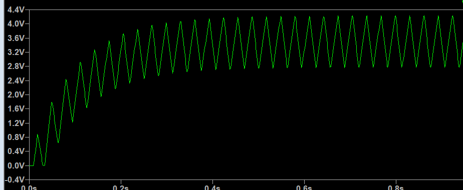
This is my output.

enter image description here

We can see that the voltage is offset too high, which is strange because per my understanding of integrators, the voltage offset should be equal to the "ground" voltage, which is 2.5V.

One way of changing this behavior is modifying the high value feedback resistor. This is an example of the resistor (R2) with a reduced resistance (200k). The closer the feedback resistor is to 0, the lower the offset.

enter image description here

I am unsure why this has such an effect on the offset voltage. Since reducing the high value feedback resistor results in a more rounded triangle wave and I don't want that (I am using the triangle for modulation on a CD4046 VCO chip,) I'm trying to figure out a way to reduce the offset voltage without distorting the triangle wave.

The LTspice model if anyone needs it. If more info is needed for this issue, please let me know.

Edit: A close-up of the square wave.

enter image description here

\$\endgroup\$
10
  • \$\begingroup\$ Previously, I asked you to wait 20 seconds for the output to settle down - have you done that? \$\endgroup\$
    – Andy aka
    Commented Mar 29, 2022 at 11:02
  • \$\begingroup\$ I did wait 20 seconds. the results were not changed. \$\endgroup\$ Commented Mar 29, 2022 at 11:10
  • 2
    \$\begingroup\$ Is that a square wave input with equal mark to space or a rectangular wave? \$\endgroup\$
    – user173271
    Commented Mar 29, 2022 at 11:17
  • 2
    \$\begingroup\$ If your square input is not "perfect" (duty cycle = 0.5 ...), you need another integrator for a feedback correction to the first integrator offset ... Without this, it will always drift ... and finally "saturate" high or low. \$\endgroup\$
    – Antonio51
    Commented Mar 29, 2022 at 11:27
  • \$\begingroup\$ An input waveform with a non 50% duty cycle will cause the integrator's output to go to an offset where the duty cycle is balanced by the discharge effect that the feedback resistor has on the capacitor. \$\endgroup\$
    – user173271
    Commented Mar 29, 2022 at 11:31

3 Answers 3

3
\$\begingroup\$

On an LTSpice simulation, I was able to improve the output waveform (V_triangle) by specifying Tr (rise time) and Tf (fall time) as 1n, rather than 0.

I checked the mark-space ratio of V_square with 0 for Tr and Tf: the waveform was visibly skewed to longer at 0 V than 5 V. When I changed Tr and Tf to 1n, the input waveform (V_square) changed to 50-50 mark-space. The output voltage then settled as a triangle centered on 2.5 V.

EDIT

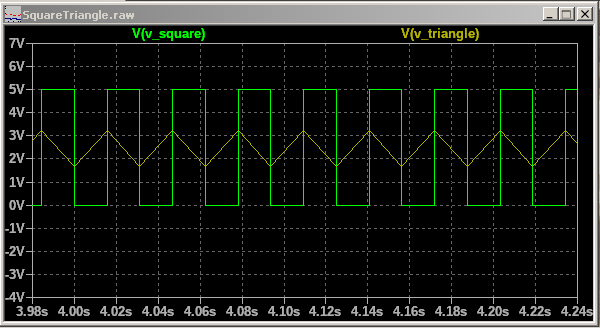
Here is my result, starting at around 4 sec. (Note that the time constant of R2*C1 is 1 sec.) enter image description here

\$\endgroup\$
1
  • 1
    \$\begingroup\$ You don't need to impose tighter tr/tf iff all you want is to see a triangle. It's enough to make Ton such that the resulting Ton+tr=T/2. Since tr=min(Ton,T-Ton)/10, you can solve this with x+x/10=1/2, resulting in Ton={5/11}. Sure enough, it works, albeit with smooth corners (due to the time**2/2 integration of the ramps). \$\endgroup\$ Commented Mar 29, 2022 at 14:12
3
\$\begingroup\$

A couple of points on LTspice: If you want continuous pulses you don't need to set the number of cycles, you can leave that blank and it will just keep going. You should set the rise and fall times, otherwise LTspice does it for you, and they probably won't be what you want. If you want them to be nearly vertical, use a very small value, 1n, 1u, or even 1p in some cases.

PULSE(5 0 0 1n 1n 0.015625 0.03125)

If you know the real rise and fall times that you are expecting from your circuit use those instead, the better the data going in, the better the results coming out.

You can improve the accuracy of the simulation by changing a number of settings and options, the most common way is to add these commands

.OPTIONS plotwinsize=0
.OPTIONS numdgt=7

If you don't specify a timestep in your transient simulation command LTspice will come up with it's own, which again will probably not be what you want. You can also delay the start of recording data to let the circuit stabilize. This statement waits 3.5 seconds, and then plots the next 0.5 seconds, with a timestep of 100uS. This will give better resolution but run slower.

.tran 0 4 3.5 100u

Try these techniques and see if they don't improve your simulations.

\$\endgroup\$
1
  • 2
    \$\begingroup\$ Specifying tr/tf to be that ridiculously low is an unneded exaggeration. If the purpose is to achieve an ideal integrator then a mathematica software is better suited. Otherwise, a value 1000x less that the period is often sufficient enough, without risking numerical issues with the solver due to the enormous dynamic range imposed to the timestep for the break points. Also, numdgt and plotwinsize are ony needed when greater than float numerical precision is required from the plots. \$\endgroup\$ Commented Mar 29, 2022 at 14:08
1
\$\begingroup\$

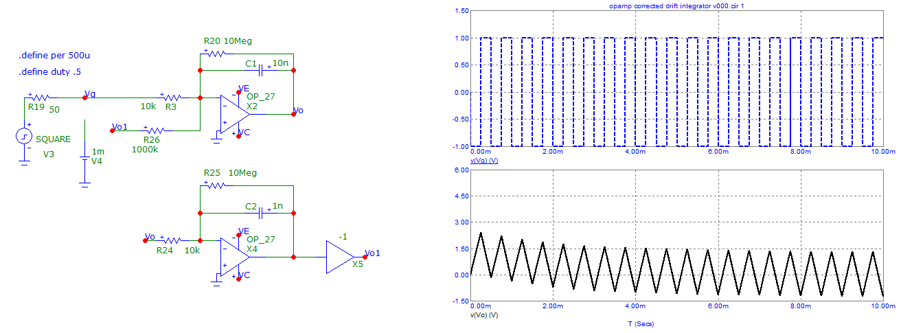
Here is a "brute force" example of "suppressing" drift in some applications.
It is used in some "opamp" amplifiers.
Used only on 50% duty cycle waveform, and perhaps (?) some others constraints ...

enter image description here

\$\endgroup\$

Your Answer

By clicking “Post Your Answer”, you agree to our terms of service and acknowledge you have read our privacy policy.

Not the answer you're looking for? Browse other questions tagged or ask your own question.