0
\$\begingroup\$

I am looking to power an Arduino from a 12 V, 5 Ah lead acid battery, hooked up to a solar charge controller. (Max output: 12 V, 20 amps). I am also looking to power a Peltier Device, in order to cool some water. The Peltier device draws 6 amps at 12 V. I am looking for:

  1. A way to limit the current drawn from the Peltier to ~3 amps. After some research, I've found the "best" method is to use a switching-regulator (constant voltage), to reduce the input voltage of the Peltier to be ~6 V, resulting in ~18 watts. (having a current draw from 2-3 amps) constant current may be a better solution, however I already have some buck-converters for constant voltage , so would like to use those if possible.

  2. Ensure that the Arduino will always receive 5 V. I am using a LM7805 voltage regulator for this. The Peltier will draw a variable current, based on its temperature, so I never want the Peltier to use so much power, that the Arduino powers off.

I am still a semi-beginner, so I apologize if my questions don't make much sense.

\$\endgroup\$
4
  • 1
    \$\begingroup\$ You are first talking about Arduino, then about Raspberry Pi... But regardless, looks like you are going to need two separate power paths with separate regulators. \$\endgroup\$
    – Eugene Sh.
    Commented Apr 4, 2022 at 18:57
  • \$\begingroup\$ It is unclear if you are just asking for confirmation for the two solutions you already found. \$\endgroup\$
    – devnull
    Commented Apr 4, 2022 at 19:07
  • \$\begingroup\$ I Guess my main question is, is there a specific component/device, that could limit the amount of current that can be drawn to a specific device. In order to ensure that other devices, connecting to the same Power Supply, can maintain their minimum power requirements. \$\endgroup\$
    – drew wood
    Commented Apr 4, 2022 at 19:12
  • \$\begingroup\$ I guarantee your battery can put out 10 amps if you want it to, although it will go flat quickly. \$\endgroup\$ Commented Apr 4, 2022 at 19:19

2 Answers 2

1
\$\begingroup\$

Your first concern is how much power the Peltier cooler needs. If you give the cooler less power, perhaps it's efficient overall, but it's still going to cool the water more slowly. Is that okay for your project?

Yes, you can use a switching regulator to efficiently convert voltage and/or current. I wonder why you don't buy a cooler that uses the amount of current you want it to use. I guess you already have the cooler and you're going to buy a regulator. I see that an 18W Peltier cooler is slightly more expensive than a 18W switching regulator, but not very much.


An Arduino doesn't use much current so a 7805 linear regulator is fine. Richard Thiessen has already pointed out that many Arduinos have built-in regulators so you might not need a separate one. If so, make sure to feed the power in a way that makes it go through the built-in regulator, so you don't break the Arduino.


You shouldn't have to think about "splitting current." You should add up all the current you need, and make sure your power source can supply at least that much. If it can't supply that much, then get a stronger power source and stop worrying about it.

Sometimes you have to deal with a weak power source and then you have to think about splitting current. But it doesn't sound like that is the case in your project.


I get the impression that you aren't really sure what happens when you draw lots of current from a battery. Basically, it causes extra voltage drop. The battery is labelled as 12V, but with low current draw, it will decrease from about 13V when full, down to about 10.5V when flat (check the datasheet). If lots of current is drawn, this also decreases the voltage a bit (check the datasheet). it will be a bit lower than that.

I guarantee your battery can put out 10 amps if you want it to, although it will go flat very quickly. Theoretically half an hour; in practice, if you discharge a battery quickly, you can't get the whole capacity, so it could be more like 15 minutes. It can probably even put out 20 amps for 5 minutes. Or 100 amps for a very short time. I'm lowballing my guesses. The datasheet for the battery should include a chart with the real numbers for your battery.

Note that if you continue draining the battery past the point of being flat, you will ruin it. You should add a way for the Arduino to detect the voltage, so it can turn off the cooler if the voltage is too low. It is possible that the solar charge controller already does this.

And I guarantee that even 20 amps being drawn from a nearly empty battery the voltage will be higher than 5V. For a 12V battery to drop down to 5V is some extreme drop. Probably the only way it can get that low is if you ruin it. No need to worry about the Arduino not getting enough voltage.

\$\endgroup\$
1
\$\begingroup\$

I am using a LM7805 voltage regulator for this.

That will work fine. although most arduinos have an on board voltage regulator that is safe to use to about 12-16V (absolute maximum is 20V but getting close to 20V is unsafe). As long as you are not drawing significant power from the 5V supply on the Arduino the on board regulator will not overheat. If you plan to do anything else. (EG:power a servo) you should use one of the DC-DC converters for that.

As long as the battery voltage remains above 7V the regulator has the extra 2V it needs to output a stable 5V for the microcontroller. The battery you are using should not drop that low in practice if you draw the 1.5A (18W/12V=1.5A) the DC-DC converter will use to power the peltier element.

I already have some buck-converters for constant voltage , so would like to use those if possible.

DC-DC converters can be made voltage controllabe fairly easily. I explained how to do this before but I'll include details in this answer. It involves tapping into the feedback pin in the DC-DC converter and driving it with a PWM signal through a smoothing network. This changes the output voltage directly.

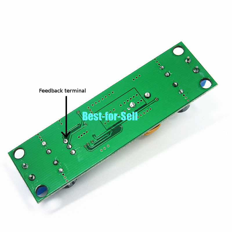
Finding the feedback pin is easy. when the converter is in operation it's usually 1.25 or 2.5 volts depending on the chip used(check the datasheet). Internally it's fed from the middle of the voltage adjustment potentiometer which is easy to find.

enter image description here

feedback terminal

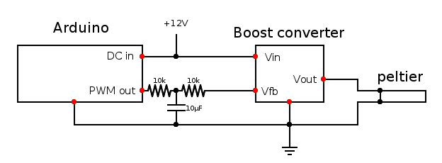
If you feed current into this pin, it changes the output voltage. Connecting it to a smoothing circuit and arduino PWM pin allows controlling the ouput voltage with a PWM signal. Note that directly connecting with just a resistor and no capacitor will turn the converter on and off at the PWM frequency and may cause problems/damage.

circuit

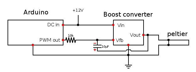
It is better however to connect the capacitor across these the Vfb and output terminals. The output terminal will likely be next to the Feedback pin on the adjustment potentiometer but you can also just wire to the terminal block, parasitic inductance is not important. This makes wiring a bit simpler and makes math or trial and error for finding component values simpler.

IMPORTANT! note the polarity of the capacitor. Positive side connects to the output terminal.

circuit 2

The Vfb pin feedback will be inverted. If the arduino outputs 5V the converter output will be lower, if it outputs 0V the output will be higher. If you set the pin to high inpedance by configuring it as an input, the converter output will be whatever is set by the potentiometer as though the converter had not been modified.

If the PWM signal gives too large a voltage swing on the output of the converter you can increase the resistors to reduce the influence of the input signal. Similarly lowering the resistor values will increase the influence of the PWM signal. You should be able to adjust the resistors and the capacitor on the converter to give the desired output range so that the maximum output voltage gives only 3A or whatever current limit you want to set.

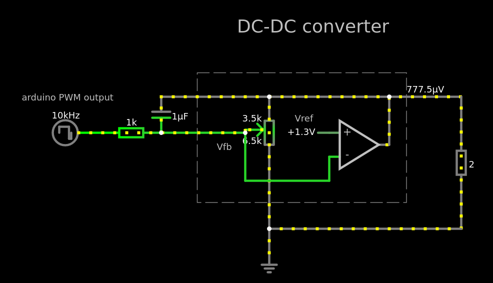
There's some math you can do to figure all this out but if you have a resistor kit, it can be faster to just try some values. alternatively here's a Falstad circuit simulator instance to play with.

enter image description here

Measure the reference voltage on the feedback pin when the converter is operating, total potentiometer resistance and check that the pot is connected to ground Vfb and Vout in the converter. In the simulation set Vfb and Rpot and you should be able to find values that work for the resistor and capacitor.

Similarly check that the capacitor and PWM frequency you are using won't cause too much ripple on the output.

\$\endgroup\$

Your Answer

By clicking “Post Your Answer”, you agree to our terms of service and acknowledge you have read our privacy policy.

Not the answer you're looking for? Browse other questions tagged or ask your own question.