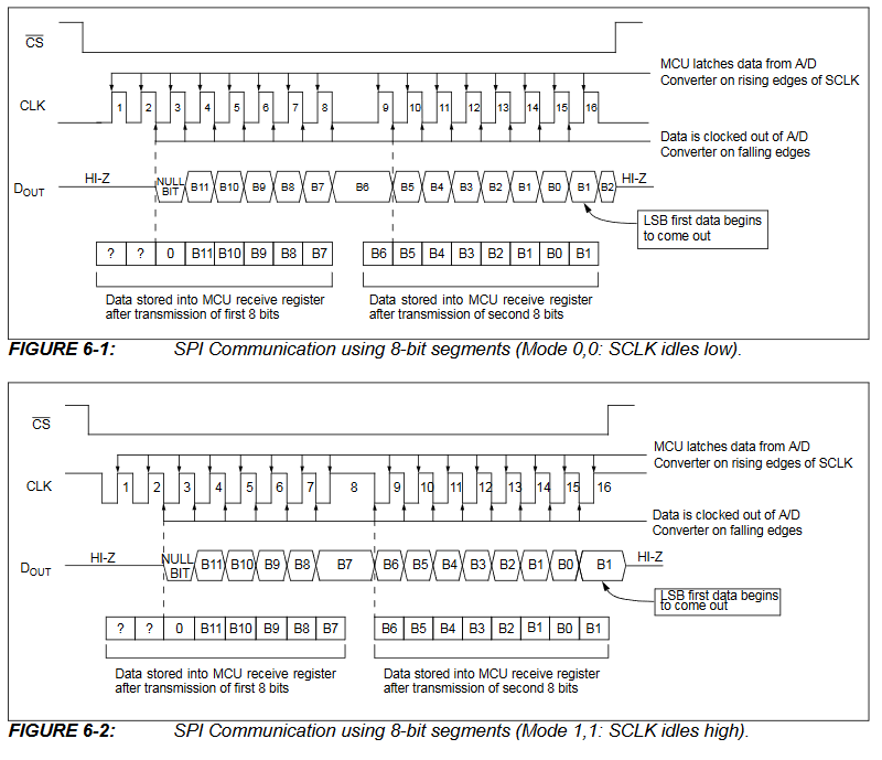
I provide the 1.2 MHz clock to SCK pin to the ADC from PIC clock pin, but how I can receive the data from MCP3201 ADC, which provides a 12 bit binary data on SPI pin SDI of PIC? Buffer of PIC is 8 bit so how I can receive the extra 4 bits from ADC?
I will share you my C code. Please check and suggest me where I can modify the code.
#include <xc.h>
#include <PIC16F72.h>
#include "config.h"
#define _XTAL_FREQ 20000000
#define SS RA5
/***************INITIALIZING LCD MODULE**************************/
#define Data_PORT PORTB
#define Enable_pin RC6
#define RS RC7
#define CTRL_PORT_DIR TRISC
#define DATA_PORT_DIR TRISB
int LSB=0,MSB=0,FINAL_DATA=0;
/*****************************************************************/
void lcd_init(void);
void LCD_command(unsigned char command);
void LCD_data(unsigned char data);
void WriteStringToLCD(const char *s);

/**********************initiAslizing SPI*****************************/
void SPI_Initialize_Master();
unsigned SPI_Ready2Read();
char SPI_Read();
/****************************************************************/
int VALUE;

void main(void)
{

   SPI_Initialize_Master();
   __delay_ms(150);

   LCD_command(0x01);
   lcd_init();
   const char msg[] = "ADC_VALUE=";
   char a= 0x30;
   LCD_command(0x80);
   WriteStringToLCD(msg);
   while(1)
   {
        VALUE = ADC_READ();
        LCD_command(0x8A);
        LCD_data(VALUE);
        __delay_ms(500);
   }

}


void lcd_init(void)
       {
        CTRL_PORT_DIR = 0x00;                           /* Direction of control port as Output                      */
        DATA_PORT_DIR = 0x00;                           /* Direction of data port as Output                         */
        LCD_command(0x38);                              /* LCD command - 5x7 matrix                                 */
        LCD_command(0x80);                              /* LCD command - Force cursor to the bigining of first line */
        LCD_command(0x3C);   // activate 2nd line
        LCD_command(0x0C);                              /* LCD command - Display ON, cursor OFF                     */
        LCD_command(0x01);                              /* LCD command - Clear display                              */
        }
void LCD_command(unsigned char command)
{
    RS=0;
    Data_PORT=command;
    Enable_pin=1;
    __delay_ms(5);
    Enable_pin=0;
}


void LCD_data(unsigned char data)
{
    RS=1;
    Data_PORT=data;
    Enable_pin=1;
    __delay_ms(5);
    Enable_pin=0;
}

void WriteStringToLCD(const char *s)
{
    while(*s)
    {
        LCD_data(*s++);   // print first character on LCD
    }
}


void SPI_Initialize_Master()
{
     TRISC5 = 0; // SDO pin set as output pin for data out
     TRISC4 = 1; // SDI pin set as data in pin s
     TRISC3 = 0; // SCK pin Set as output
     TRISA5 = 0; // SS pin set as output pin for slave select
     TRISB = 0x00;
     SSPSTAT = 0b00100000; // data transmittend on falling edge of clock cycle
     SSPCON = 0b00100001; //pg 75/234  idle state for clock is low level & fosc/16
     SS = 1;

}

int ADC_READ(void)
{
       SS = 0;
       SSPBUF = 0x01; // Initiate SPI bus cycle
       SSPSTATbits.BF = 0; // CLEAR THE BUFFER BIT
       while(!SSPSTATbits.BF);
       __delay_ms(10);
       MSB = SSPBUF;
       __delay_ms(10);

       SSPBUF = 0x81; // Initiate SPI bus cycle
       SSPSTATbits.BF = 0; // CLEAR THE BUFFER BIT
       while(!SSPSTATbits.BF);
       LSB = SSPBUF;
       __delay_ms(10);
       SS = 1;

       LSB=(LSB>>1);
       MSB=(MSB<<7);
       FINAL_DATA = MSB+LSB;
       return(FINAL_DATA);
}

