2
\$\begingroup\$

I am designing a 40 kHz bandpass filter for a university project involving a portable ultrasonic device. I have designed a 40 kHz filter using the Linear Technology Filter Design Tool with a single rail op amp (due to design being powered by 9 V battery, stepped down to 5 V using LF50 voltage regulator). The circuit was then built in LTSpice and simulated using an AC sweep. Below is the LTSpice circuit as well as simulation results, which are exactly as desired. (Note: LTC6255 used in simulation, MCP 601 used in actual circuit.)

circuit results

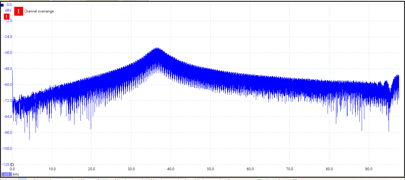
The circuit was then built on stripboard and tested using a AFG-2105 function generator to perform an AC sweep from 1 Hz to 100 kHz with Vpp = 7 mV. A Picoscope was used to read the waveform.

pico circuit

As you can see, the test results do not come close to the simulated results.

Any ideas what I might be doing wrong?

I checked ground connections, retested and got the following result:

result

\$\endgroup\$

1 Answer 1

2
\$\begingroup\$

You're not measuring a circuit that does anything. Look at the scale of your measurement: -65 dBu is less than a millionth of a microvolt, so, nothing. Check your supply voltage, signal and ground connections (especially: make sure the measurement ground is tightly coupled to your system ground), make sure your opamp is enabled and not damaged/non-functional at arrival.

Things to check, because I'm not happy with your circuit ;)

  • what does the spectrum of VDD look like? The LF50 is not a great regulator.
  • Also, your VREF design doesn't look that great: your VREF source impedance is > 3.3 kΩ, so feeding in something with a ~9kΩ source impedance will significantly pull VREF around, so observe the spectrum of VREF as well. You could stabilize VREF with another voltage follower (note that not all opamps deal well with capacitive load!), or actually use a fixed voltage reference
  • The MC601 has some 2mV offset voltage, but the signal you're feeding in has only 7mV amplitude. Try to recreate with a higher input amplitude.
  • You filter has an attenuation of no more than 23 dB in simulation. This seems underwhelming for an active filter. If you wanted that, a passive one might have sufficed?
\$\endgroup\$
2
  • \$\begingroup\$ Thank you very much for your response. I have resoldered the ground connections and made sure measurement ground is tightly coupled to system ground. I am also using a 0.2Vpp input voltage. In my post edit I have uploaded the new results. It is much closer to my desired result. Might I assume that changed to VREF, in addition to more bypass capacitors, would further improve performance? \$\endgroup\$
    – LK26
    Commented Apr 6, 2022 at 11:18
  • \$\begingroup\$ @LewisKell What is the actual time-domain step response of your circuit? Compare to theoretical values, just as you did with the frequency-domain response. Frequency-domain is fine to look at once you've satisfied yourself that the voltages actually look sensible. The channel overrange warning is significant as well: you're saturating the scope. \$\endgroup\$ Commented Apr 6, 2022 at 11:55

Your Answer

By clicking “Post Your Answer”, you agree to our terms of service and acknowledge you have read our privacy policy.

Not the answer you're looking for? Browse other questions tagged or ask your own question.