0
\$\begingroup\$

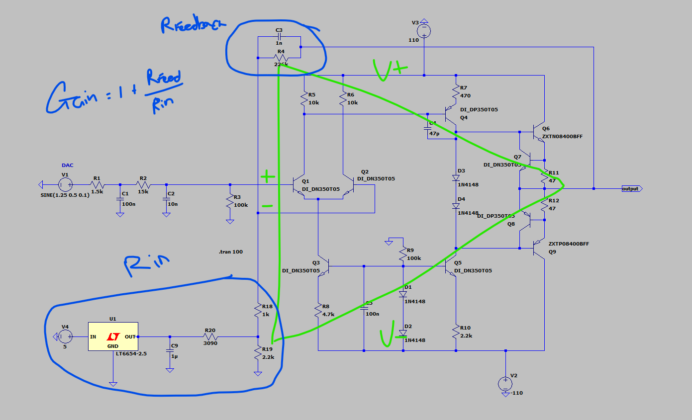
I'm working with a three-stage BJT amplifier that takes an input from a DAC with a full-scale output voltage of 0-2.5V.

I've been told from probing the output the gain is somewhere around 100. I was wondering how I went about calculating the gain of the amplifier? Can I just treat it like an opamp and say

Gain = 1 + Rfeedback/Rinput?

Or would I have to calculate the gain of each stage?

enter image description here

I've simulated the model in LTSpice and it kind of works, although I'm not sure if this is just a coincidence.

On the trace I've cantered both input*gain and output to show how similar they are. My other question would be, how does the DC offset get removed when the signal goes through the amplifier?

enter image description here

Any help or links to resources would be great!

\$\endgroup\$
4
  • \$\begingroup\$ err V2 is shown +ve. Show your design specs and assumptions for Aol. \$\endgroup\$
    – D.A.S.
    Commented Apr 7, 2022 at 13:49
  • \$\begingroup\$ 1) Understand the condition that lets you use that formula for an opamp, and calculate whether (or how closely) your design meets that condition. 2) See what U1 does. \$\endgroup\$
    – user16324
    Commented Apr 7, 2022 at 13:52
  • \$\begingroup\$ Gain formula is reduced by the amount of open loop gain/ closed loop R ratio roughly \$\endgroup\$
    – D.A.S.
    Commented Apr 7, 2022 at 17:34
  • \$\begingroup\$ I hope you have massive heatsinks for a +/-100V swing in some load TBD \$\endgroup\$
    – D.A.S.
    Commented Apr 7, 2022 at 20:07

1 Answer 1

2
\$\begingroup\$

First, it's a very basic amplifier and you may have some non-linear response output vs input. It will be much better to use a precision op amp if your ADC is making measurements where the absolute output is important. If you are running a PID control system that is self-correcting, you should be fine.

Yes, in general, the equation is the same as an op amp and, if you look at an op amp detailed schematic, you'll see a very similar design with the long-tailed pair taking the input and feedback with some type of push-pull output pair as you have.

If you are really only driving an ADC with this amplifier, you really don't need the third stage output power transistor stage on the far right.

\$\endgroup\$
1
  • 1
    \$\begingroup\$ Also, R18 should be 10x or so larger than either resistor in your voltage divider virtual ground made with your 2.5v reference and R19+R20. Otherwise R18 will become part of the voltage divider network and your reference voltage and gain can shift - especially if your feedback resistor is changed to lower gain or current draw from the base of Q2 is significant. \$\endgroup\$ Commented Apr 7, 2022 at 14:00

Your Answer

By clicking “Post Your Answer”, you agree to our terms of service and acknowledge you have read our privacy policy.

Not the answer you're looking for? Browse other questions tagged or ask your own question.