2
\$\begingroup\$

I've been trying to simulate a central-tap transformer in LTspice. However, whenever I run a simulation an error message appears:

"Rser: Missing node(s)"

Could someone please explain to me what this error message means and what I can do to fix it. Thanks.

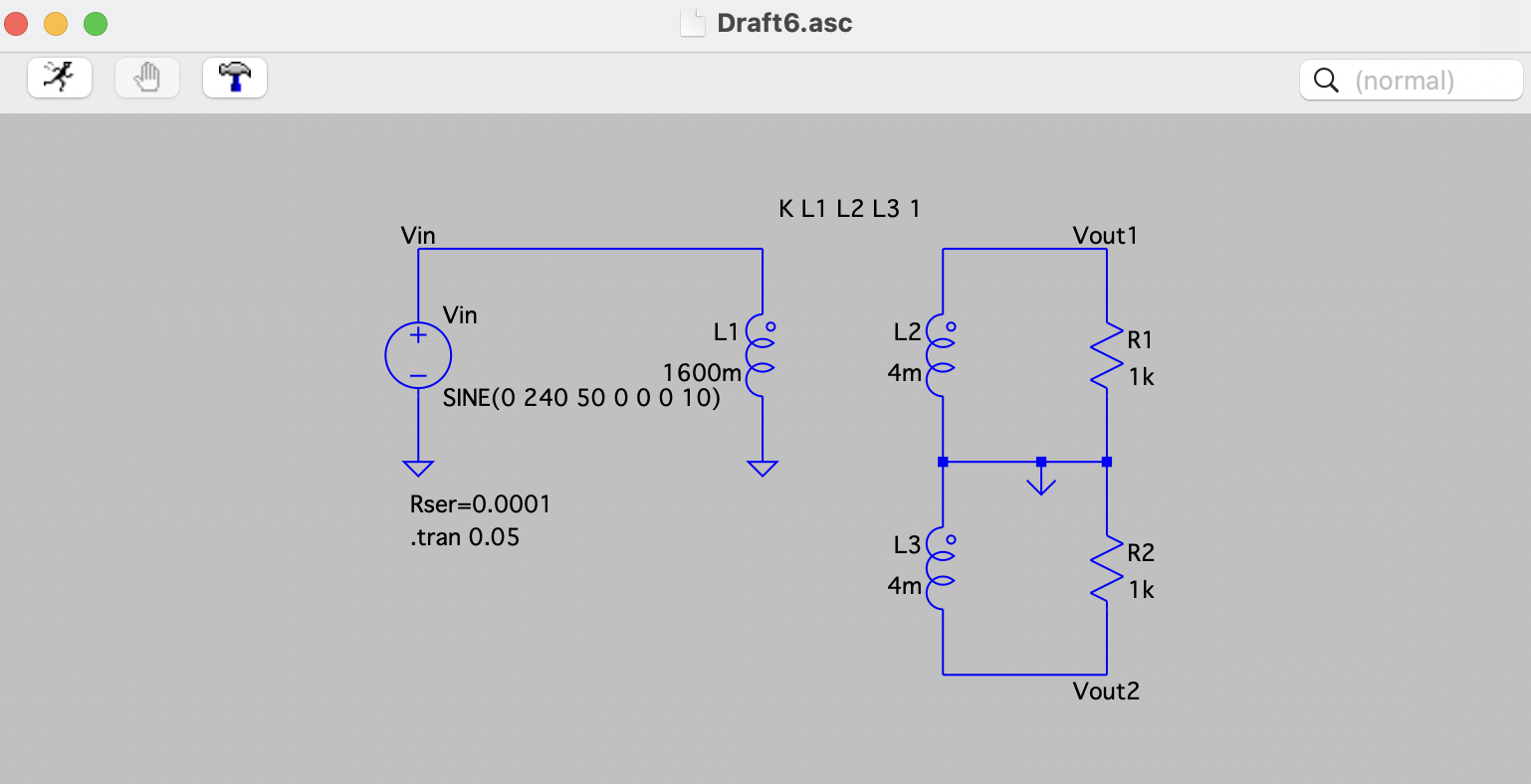
Circuit diagram

\$\endgroup\$
4
  • 1
    \$\begingroup\$ Post a netlist file \$\endgroup\$
    – Voltage Spike
    Commented Apr 7, 2022 at 16:42
  • \$\begingroup\$ Is primary Rser reference missing? Where is DCR for L1? L/R is too big ?? \$\endgroup\$
    – D.A.S.
    Commented Apr 7, 2022 at 17:07
  • \$\begingroup\$ Wait, which version of LTspice is this, and is that MacOS; which version? Or Linux/Wine? Icons are very different from Windows, and the right-most ground symbol is "interesting." \$\endgroup\$
    – rdtsc
    Commented Apr 7, 2022 at 18:02
  • \$\begingroup\$ @rdtsc OP used the COM "ground", which is not the ground, just a visual gimmick for something different that ground, which means the whole secondary is floating. LTspice XVII tries to avoid users shooting their own feet by adding some Gmin. Personally, I disagree, but it's gaining traction due to commodity weighing heavier than responsability. \$\endgroup\$ Commented Apr 7, 2022 at 18:16

3 Answers 3

5
\$\begingroup\$

This is telling you the Rser=0.0001 statement is trying to set "Rser" to a value, but "Rser" is not used anywhere in the schematic.

If you're trying to set the series resistance globally, this does not work in LTspice.

Right-Click each component and set the series resistance for each component. OR, set each component's series resistance to {Rser} - then it should work globally.

Also, you can Ctrl-Right-Click a component and enable/disable the display of this resistance if desired.

\$\endgroup\$
3
  • \$\begingroup\$ Unless the OP added that line to the schematic themself, Rser is the series resistance of the voltage source, if you set it under the source's parasitic properties it will show on the schematic like that unless you uncheck 'make this information available on schematic'. \$\endgroup\$
    – GodJihyo
    Commented Apr 7, 2022 at 17:33
  • \$\begingroup\$ Ah, it looks like the did add that to the schematic. It looks exactly what you would see if you set the voltage source's Rser, but it's not. If I add that to my schematic I get the same error. \$\endgroup\$
    – GodJihyo
    Commented Apr 7, 2022 at 17:36
  • \$\begingroup\$ If OP wants a parameter, .param Rser=0.1m is a better choice. \$\endgroup\$ Commented Apr 7, 2022 at 18:17
3
\$\begingroup\$

Check your netlist file and see what Rser actually is (best thing to do when debugging). If its floating text, and not associated with the Vin, then spice would insert it as a line in your netlist file and consider it a resistor with no nodes attached.

The series resistance is defined in the voltage source dialog box.

\$\endgroup\$
2
\$\begingroup\$

I set up the same schematic.

I thought that Rser was part of the voltage source, if I set Rser in the source I see that line on the schematic, and everything works okay.

I then tried adding that line as a spice directive and got the Rser: missing nodes error, so that must be what is causing it. Delete that from the schematic and try it.

Give credit to rdtsc's answer, which led me to try that.

\$\endgroup\$

Your Answer

By clicking “Post Your Answer”, you agree to our terms of service and acknowledge you have read our privacy policy.

Not the answer you're looking for? Browse other questions tagged or ask your own question.