Firstly, apologies for what I am sure is an incredibly novice question -- I have very little general electronics experience.
Having previously built my home/hobby PCs from pre-existing components, cases, cables, etc. I am currently attempting a very custom build with a bespoke case and an unfamiliar motherboard.
The motherboard documentation (page 33 onwards) describes the pin header of the front-panel case connectors. It has the usual power and reset switches, and power and HDD LEDs, which I am familar with, as they are common to most cases. All of these use a standard, two-pin Dupont-type connector, and look to be easy enough to wire in with a kit (presuming I can get my +/-, ground, standby, etc. terms the right way around). Similarly, it has two NIC activity LEDs, which look to be the same as either the power or reset LEDs.
However, the front-panel header also includes pins for what appears to be a multi-state indicator for identification and alerting for overheat/fan failure conditions, where it can be:
- off (no issue)
- solid orange/yellow (overheat)
- flashing orange/yellow (fan failure)
- solid blue (identification)
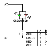
I appreciate I can run without it but, if I were looking to be completist, I am struggling to determine what that indicator is and how it would wire in. It looks to only require two pins, although it labels these as simply Pin 7: Blue UID LED; Pin 8: OH/Fan Fail/PWR Fail LED (where the others have Pin x: +3.3 Stby; Pin y: the LED). I'm guessing these aren't some kind of single-pin LEDs, because surely they need both a + and - connection of some kind?
I expect that, if I were to use a chassis/case from the same manufacturer, it would be an proprietary/embedded part of that case, but for a bespoke build, I'm not sure what I could substitute.
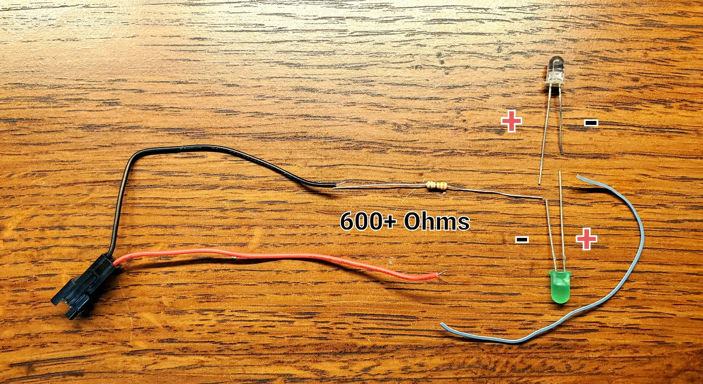
I can certainly see various bi-colour LEDs for sale, but I assume it is not likely to be a simple as soldering one onto a pair of wires and crimping a Dupont connector on the end? I'd guess there'd have to be a small custom board, the correct resistance, some microcontroller to handle amber/blue, on/off/flash based on...voltage(?)
Given the information available, is there enough to determine what should be used here (and, if so, what); or is somehow acquiring or salvaging the proprietary board from a manufacturer's chassis the only real option (besides running without)?


