Searching Amazon for a PWM controller board I found this:
https://www.amazon.com/dp/B07MH43SXR
Apparently, they are 6 MOSFETs. I understand that an H bridge is built with 4 MOSFETs. Is there any other common drive circuit that would use 6 MOSFETs?
Searching Amazon for a PWM controller board I found this:
https://www.amazon.com/dp/B07MH43SXR
Apparently, they are 6 MOSFETs. I understand that an H bridge is built with 4 MOSFETs. Is there any other common drive circuit that would use 6 MOSFETs?
I would not assume that's an H-bridge. Nothing in your link says it's an H-bridge or that it is capable of bidirectional control and the crude potentiometer control would also not be suited for an H-bridge since the zero point between forward and reverse is poorly defined.
To control a brushed DC motor unidirectionally is very easy...you just throw a MOSFET in series with the motor and put as many in parallel as required for the current. With a 40A rating, I could easily see this being the case.
I would expect an H-bridge that supports 40A involves considerably more components than what I am seeing here, even though the underside of the PCB is hidden.
The driver could be a single-direction "chopper", with all 6 mosfets in parallel.
A symmetric H bridge would need multiples of 4 mosfets, but for this application a symmetric H-bridge is unnecessary.
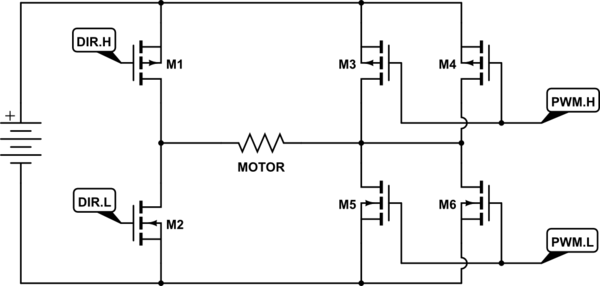
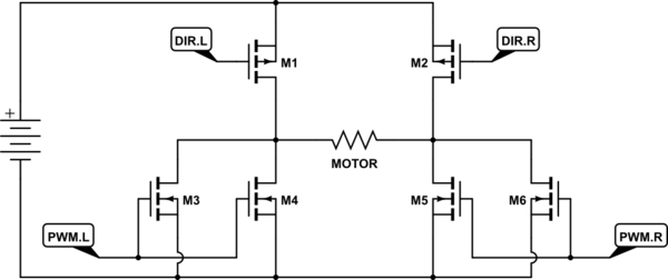
It could be an H-bridge with just one half controlled by PWM, and the other half acting as static direction switches. The direction switches can be optimized for low on-resistance, but can be slow - a typical tradeoff in MOSFETs. The other half of the bridge can be paralleled higher resistance but faster devices.
For example:

simulate this circuit – Schematic created using CircuitLab
Even if all the P/N mosfets are identical, M1 and M2 won't experience switching and gate drive losses, so may run cool enough that single devices are sufficient. Then M3+M4 and M5+M6 are driven with PWM, and dissipate more power, and thus are paralleled.
The same thing could be accomplished in a top-bottom split, as noted by nkgyuen:

The worse-performing PMOS switches M1,M2 could be selected for sufficiently low RDS(ON) without concern for gate capacitance. The faster, lower-resistance NMOS devices M3-M6 would have no trouble dealing with all the switching.
If that's how indeed this device is designed, I'd consider it at least somewhat clever.
I am guessing it is for driving a brushless DC motor. These motors are wound to accept 3-phase power in a Wye or Delta configuration. The 3 sinewaves are produced by 3 complimentary pairs of Mosfets with PWM inputs to generate the 3 sinewaves.