4
\$\begingroup\$

Just for fun, I used an LM317 IC with two resistors (1.5k and 470 ohm) to get an output voltage of around 1.8 volts and used this circuit with a wall clock.

It worked amazingly well when I connected different batteries, such as 3.7V, 6V and 12V, but when I connected charger to the battery, I soon found that the speed of the wall clock was noticeably faster than normal and it was ahead of my wrist watch after just a few minutes.

I repeated the experiment with two other LM317 ICs using different wall clocks, and the result was the same. I used another pair of resistors and output a voltage of around 1.5V, still the same result.

Then I used AMS1117-1.5 IC and the wall clock was still running much faster than normal.

I don't understand why this happens when I connect charger to the battery.

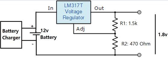
The circuit I designed was like this:

enter image description here

\$\endgroup\$
11
  • 5
    \$\begingroup\$ Please, provide a schematic of the exact circuit you are using, with the specification for every part. Moreover show how you connected the charger to the battery (the circuit with the LM317 was still attached?). \$\endgroup\$ Commented Apr 17, 2022 at 15:27
  • 1
    \$\begingroup\$ I have added a diagram of the circuit. Moreover, It is clear from the question that the charger and the load both were attached at the same time. It worked fine when the charger was not attached, when the charger was connected, the circuit malfunctioned. \$\endgroup\$
    – Asmat Ali
    Commented Apr 17, 2022 at 16:27
  • 2
    \$\begingroup\$ Exactly which charger were you using? How long are the wires from the battery to the LM317? What happens if you only connect the charger's negative lead (so it's connected to the battery but not charging it)? Can you show us a photo of the entire setup? \$\endgroup\$ Commented Apr 17, 2022 at 20:29
  • \$\begingroup\$ 1. You are missing all the capacitance recommended in the datasheet. 2. The maximum allowed value for R1 is 240R. The regulator cannot start with the value you have. \$\endgroup\$
    – user207421
    Commented Apr 18, 2022 at 10:17
  • \$\begingroup\$ @user207421 I have tested the circuit with 4.7uF capacitors and it didn't improve the performance in any way. \$\endgroup\$
    – Asmat Ali
    Commented Apr 18, 2022 at 12:46

4 Answers 4

3
\$\begingroup\$

Other replies and chats presented some reasons for the problem you mentioned:

... It worked amazingly well when I connected different batteries, such as 3.7V, 6V and 12V, but when I connected charger to the battery, I soon found that the speed of the wall clock was noticeably faster than normal...
I don't understand why this happens when I connect charger to the battery.

Possible reasons:
As we don't have the exact details as some other requested, we can mostly speculate.
I believe there is a combination of effects/issues that are superimposed to the results found:

  • Minimum Load Current: LM317, like other series regulators, require a minimum load current, which vary from model to model. In case of the LM317, using 120 Ohm as R1 provides the required 10 mA for the worst case condition.
  • Transient response of LM317: The LM317 might operate with a lower Load than 10 mA, but transient response and its output voltage may be compromised. This could explain why LM317 works with battery as smoothest power supply, but may not respond well to transients.
  • Noisy Charger: Most Battery chargers are electrically "noisy", with rare exceptions.
    Simple battery chargers can even feed the battery with pulsed DC, which is not even filtered, using a diode only, without capacitors!
    Other "smart chargers" can use switched mode power supplies SMPS, but count on the voltage-smoothing effect of the battery. SMPS can cause a high-frequency "ripple", usually in the 20KHz-100KHz range.
    Transient response of LM317 is better for low frequency (rectified line = 60-120Hz) than for poorly filtered voltages from a SMPS in certain chargers (that is why readers asked about the charger model).
  • Internal Resistance of Battery: 12V Battery can have a higher internal resistance compared to the pulsed charging current. It could a motorcycle battery (5-10Ah) or an aged car battery. In both cases, internal resistance could be as high as 50 milli-Ohm. Let's say charging pulses are 10A; in this case, the charging ripple would be 500 mV.
    If LM317 was properly loaded, its attenuation would be about 60 dB, so output ripple would be negligible.
    But your circuit drains just 1.25/1K5 = 0.83mA = 8% or the minimum required (worst case).
  • Clock circuitry under Pulsed voltage supply: most digital clocks are battery powered and do not have enough protection against pulsing supply voltage. Such pulses could perturb the quartz timing and divider, by creating extra clocking pulses, making your clock run faster than expected. Minimizing any overvoltage - pulsed or not - should be a priority.

Ways of Investigation:
If you have a cheap portable oscilloscope (as DSO138), it would be a great tool to see the behavior of any voltage transient.
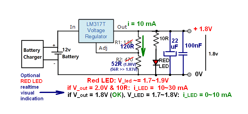
But if you don't have any, don't worry: Try to use a RED LED as here:
enter image description here

I assume the Red LED voltage is 1.7V; other colors have different threshold voltages.
For V_out = 1.8V, LED will light up dimmly with a 10_Ohm resistor. "Memorize" the light intensity using just the 12V battery.
Then connect and power the charger. If the LED changes its light intensity or starts pulsing, that is the evidence the LM317 is not operating correctly. I used your drawing and made a small revision and upgrade.

About the Revised Circuit:
Resistor values: To avoid the improper operation of the LM317, I changed resistor values R1 and R2; R1 = 120R and R2 = 52R (or 56R, if 1.83V is Ok). This is the revised value of R2, with the comment/help from OP. Two capacitors - electrolytic and polyester/ceramic - would help the transient response too.
RED LED could be omitted but is a visual indication that all continues to work right.

Obviously, the circuit could be designed differently, from the selection of the series regulator to the charger circuitry, but that would be another question. So I believe I have addressed the most likely reasons for the findings identified.
Let us know about the RED LED behavior (investigation) and if the changes proposed worked as intended.

Update and Feedback from OP:
The Original Poster - Asmat Ali - helped me to identify a mistake in R2 calculation - thanks! He also mentioned the problem was solved using (my additions):

After adding a 4.7uF capacitor there (output), the circuit worked perfectly with (R1) 1000 and (R2) 470 ohm resistors.

While the circuit could now work just adding the output capacitor, the load current is still too small and I recommend the minimum load is increased.
A minimalistic suggestion is adding to the original circuit R_Load = 180R, providing the worst-case minimum current of 10 mA (@ 1.8V), while keeping that 4.7uF OP mentioned.

\$\endgroup\$
3
  • \$\begingroup\$ Thanks for the detailed answer. In my case, the problem was actually due to not using a capacitor on the output side of the circuit. After adding a 4.7uF capacitor there, the circuit worked perfectly with 1000 and 470 ohm resistors. I am curious to know why you changed R2 to 1k6? 120 and 1k6 give an output of about 17 volts according to the formula. \$\endgroup\$
    – Asmat Ali
    Commented Apr 24, 2022 at 13:19
  • 1
    \$\begingroup\$ About your findings, good to know the Output Cap improved the performance to make it stable. And about the R2, surely I did a mistake, probably due to late night calculation. Glad that you got it, thanks. The correct value should be R2 = 52Ω. This is just a quick reply, as I the drawing and text to this 52R value are in the PC, now it is very late, so I may need a couple of days for that. You mitigated the instabilities with the Output Cap, but I still believe R1=120R + R2= 52R or at least a larger load as 180Ω at 1.8V could improve LM’s stability for all conditions. \$\endgroup\$
    – EJE
    Commented Apr 27, 2022 at 5:13
  • 1
    \$\begingroup\$ @AsmatAli, please see my revised Answer - Picture and Text - considering your feedback and comments. Thanks again for helping to find the R2 mistake. I included a mention of a minimalist solution (R_load = 180R), based on our latest interaction. If you consider I have addressed what you asked, please consider accepting the answer. And if you could try the LED on the original circuit and confirm (or not) the suspicions, your experiment will allow us all to learn from it. \$\endgroup\$
    – EJE
    Commented Apr 27, 2022 at 14:45
7
\$\begingroup\$

LM317 is transparent to AC currents produced by switching power converters. The spikes produced by the charger go straight through the LM317 into the clock circuit, and easily overpower the crystal circuits that works at 1uW power level. The clock is counting some of the spikes from the charger as if they were pulses from the quartz oscillator.

If you had used a linear charger, you wouldn’t have this problem, but most chargers use switching power converters for efficiency and expeditiousness of design.

\$\endgroup\$
3
  • 1
    \$\begingroup\$ That's because he is missing the recommended capacitance, not specifically because of the switching PSU. \$\endgroup\$
    – user207421
    Commented Apr 18, 2022 at 10:18
  • 2
    \$\begingroup\$ @user207421 That may well be too, but watches are quite-sensitive to power supply junk. They are micro power circuits with noise suppression only sufficient to deal with radiated susceptibility. If you feed them conducted noise on the battery input, they are not designed to deal with that. There’s also a lot of variability between watch models – I’ve personally seen an order of magnitude differences in susceptibility at least, and the very expensive watch wasn’t the better one, curiously enough. It never had problems when running off the battery with the metal back closed. \$\endgroup\$ Commented Apr 18, 2022 at 13:19
  • \$\begingroup\$ Certainly. So are lots of things. I haven't claimed otherwise. But the whole point of the question is that the regulator should have removed the power supply junk, and the answer is that it will if an input capacitor. is used, and a proper value for R1. \$\endgroup\$
    – user207421
    Commented Apr 22, 2022 at 0:39
5
\$\begingroup\$

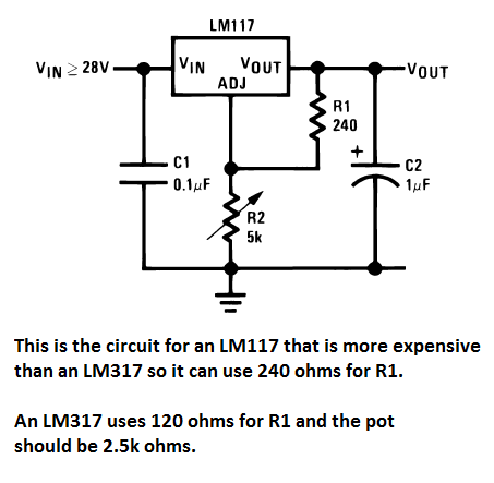
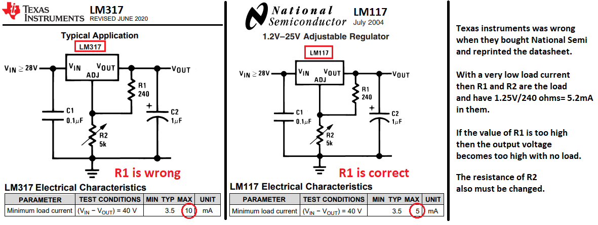
The problem is that the old LM317 needs to have a load of at least 10mA for it to regulate the output voltage. Your 470 ohm resistor has too much resistance for an LM317. The datasheet shows 240 ohms for the more expensive LM117 and 120 ohms for the LM317. The datasheet also shows important input and output capacitors.

Then you also must reduce the resistance of the 1.5k to 51 ohms for the output voltage to be about 1.78V.

LM317

\$\endgroup\$
4
  • 3
    \$\begingroup\$ This doesn't really explain why it worked with batteries and not the charger. The difference occurred for both the LM317 AND LM117. \$\endgroup\$ Commented Apr 17, 2022 at 16:59
  • \$\begingroup\$ I would also add some bulk capacitance parallel to C1 on the input. \$\endgroup\$
    – Gil
    Commented Apr 17, 2022 at 22:13
  • 1
    \$\begingroup\$ 240R is the maximum value of R1 for both 317 and 117. The datasheet shows numerous examples of 240R for the LM317. You are extrapolating from a single sample, and you are also confusing R1 with R2. \$\endgroup\$
    – user207421
    Commented Apr 18, 2022 at 3:57
  • \$\begingroup\$ The datasheet numbers are quite clear on the minimum load- it is NOT guaranteed to regulate with a 240 ohm R1 and no load. It typically will, however, so people get away with it. Worst case is low temperature and high Vin-Vout. But it's not good design to depend on typical specifications, not at all. \$\endgroup\$ Commented Apr 23, 2022 at 1:38
1
\$\begingroup\$

If you use the maximum resistor value for the LM317 then some of them will have the output voltage rise if its load current is low.

LM317

\$\endgroup\$

Your Answer

By clicking “Post Your Answer”, you agree to our terms of service and acknowledge you have read our privacy policy.

Not the answer you're looking for? Browse other questions tagged or ask your own question.