8
\$\begingroup\$

I have an FPGA dev board with a fan PWM circuit so that you can hook it up to a fan + heatsink. I happen to like this as we put a common heatsink together for the hottest components, and I drive it from the FPGA based on the FPGA's internal temp.

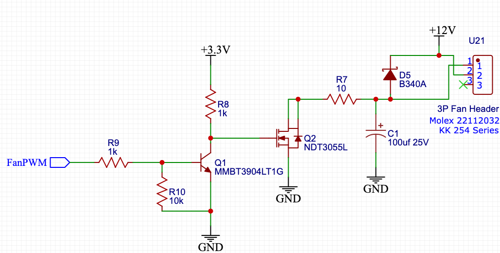
Now we're looking to build the first iteration of our own PCB. I have made a "highlights" schematic showing basic connectivity and some of the support circuits for elements outside the FPGA. I will soon be handing this schematic to our real electrical engineer. The fan PWM support circuit is one on my "quasischematic," and I basically had to reproduce it from the dev board's schematic. Shown here:

FanPWM Circuit

I think I understand most of this. R8, R9, R10, and Q1 are there to take the relatively small CMOS 3.3V signal of the FPGA (FanPWM) and turn it into something high enough current to drive the power MOSFET. R7 is a current limiting resistor, preventing a 100% duty cycle from letting the fan draw more current than it can handle. Q2 is the power MOSFET that acts like the "on-off" switch that sits between the fan and the ground.

Here's the part I am confused about. What is the reason for the Schottky rectifier and the polarized capacitor? I only have one idea about the diode, which seems odd to me. The capacitor I have two ideas, but neither seems right.

Diode Idea: ESD So I thought that maybe the diode was for some static protection between 12V and the other stuff. But that seems odd because, without it, the fan should act as a large inductor any instantaneous spike due to ESD or inrush current when the 12V supply is connected should be stopped by the fan, and frankly, anything not blocked by the fan will bypass the diode anyways.

Capacitor Idea 1: Power Supply Filtering This idea seems unlikely because the capacitor is polarized, has a relatively large value, and is not in parallel with at least one other cap. The other power supply filtering capacitor arrangements I see elsewhere are frequently 10uF in parallel with 0.1uF or 2.2uF with 10nF. Here we might have low frequency covered but not high frequency, and the polarization is odd. Further, this is not between 12V and ground.

Capacitor Idea 2: Energy Storage / Pulse Smoothing I thought maybe a large capacitor like that might be storing energy to "smooth out" the sharp pulse edges. But that seems odd to me as this is on the ground side of the fan.

So my question is: what is the purpose of the diode and capacitor in this circuit?

\$\endgroup\$
0

2 Answers 2

13
\$\begingroup\$

Motors are inductive loads. When you apply PWM to a motor, it generates high voltage spikes. The purpose of the diode is to shunt the energy from these spikes back to the supply instead of the transistor. The diode is called shunt diode or free wheeling diode. The capacitor helps absorbing some of the energy and slow down the transients.

\$\endgroup\$
3
  • 1
    \$\begingroup\$ The very first sentence I knew. I hadn't realized the rest. But when I look for it in the V=-L*dI/dt equation for inductors it's pretty obvious. Current is falling fast, the inductance is pretty high, boom big voltage spike. I am so used to thinking of inductors as blocking high-frequency spikes from passing that I didn't think about the fact they could generate them when DC current was abruptly withdrawn. Thank you! \$\endgroup\$ Commented Apr 23, 2022 at 17:53
  • 2
    \$\begingroup\$ The connector on the right says it goes to a molex fan, molex fans don't behave like inductors, but are rather their own board with a custom switching fan controller. These do not generate high voltake spikes \$\endgroup\$
    – Ferrybig
    Commented Apr 23, 2022 at 20:29
  • 4
    \$\begingroup\$ @Ferrybig After I saw this answer I did a little more research armed with the proper terminology. So, while what you say is certainly true for DC brush-less motors, the 3-pin molex adapter doesn't guarantee the use of a DC brush-less motor. For PC fans, it's nearly guaranteed. That's said, the 3-pin molex connector doesn't prevent two pin fans from being used nor odd adapters. As I said above I reproduced the circuit from the dev board, the dev board people make no specifications to the fan. So they have to design the circuit as able to handle any kind of fan load. \$\endgroup\$ Commented Apr 24, 2022 at 3:09
3
\$\begingroup\$

Your ideas 1 & 2 for the capacitor are both partially correct. The capacitor, MOSFET, and resistor form a type of variable DC power supply. As the PWM switches Q2 on and off the capacitor and 10 ohm resistor filters or smooths out the sharp pulses into more of a DC voltage, the capacitor also stores energy between pulses (after passing through the fan). In this case the voltage on the capacitor changes from +12v to near 0v as Q2's turn on time increases, (so as a result the fan terminals see about 0v to 12v as Q2's turn on time increases).

With the large value capacitor the fan motor will not see much of the original sharp pulses. However, there could be some voltage spikes if the fan motor quickly changes from fast to slow and when it stops completely, so the diode can eliminate any reverse voltage spikes by shunting them across the motor pins. Some higher quality fans might even have a diode (and maybe even a small capacitor) already mounted close to or on the actual motor terminals.

Another design issue, since you have the +12v at the center of a 3 pin header connector (U21) you could route pins 1 and 3 together. That way the polarity of the connection becomes sort of fool-proof. If assembling your own wiring to the fan you could even save a small cost by going to a lower cost non-polarized connector.

.

\$\endgroup\$
1
  • \$\begingroup\$ Thanks for making the capacitor's utility in suppressing the voltage surges clearer. As to the 3-pin fan connector, that's an industry standard connection for a lot of computer fans. It's easy to find fans with that 3-pin connector. Further the 3rd pin, unconnected in the posted schematic, is a tachometer signal from the fan. While we don't plan on using it right now, shorting it directly to ground is probably not the best idea. \$\endgroup\$ Commented Apr 23, 2022 at 19:30

Your Answer

By clicking “Post Your Answer”, you agree to our terms of service and acknowledge you have read our privacy policy.

Not the answer you're looking for? Browse other questions tagged or ask your own question.