0
\$\begingroup\$

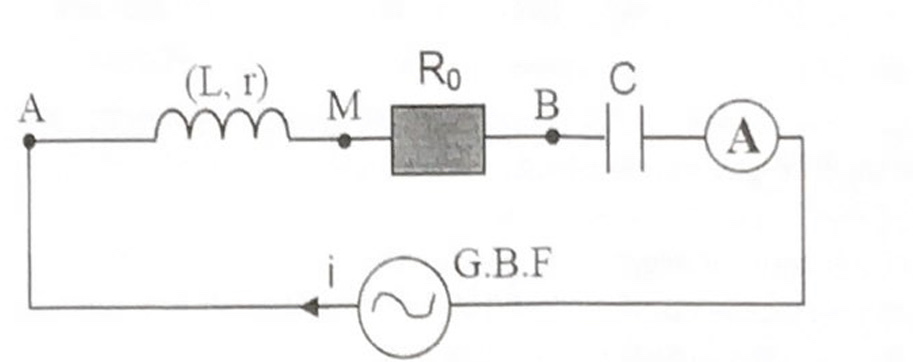
Here I have a series LCR circuit with resonant frequency greater than 200Hz. Is there a way to know whether this circuit is an inductive or a capacitive load?

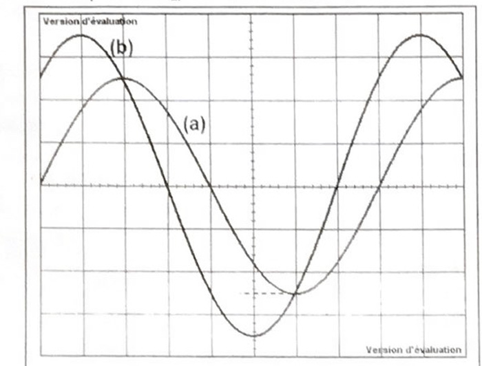
Edit: The only additional information we have is the phase shift between the inductor (with resistance r) and the resistor which is +45 degrees.

Here is the schematic:

enter image description here

Below are plotted voltages of the inductor (plot b) and the resistor (plot a.). The X-axis refers to the time with scale π/4 by division and Y-axis represents the voltage with scale 1V by division.

enter image description here

\$\endgroup\$
3
  • 1
    \$\begingroup\$ Welcome! Please embed a schematic. \$\endgroup\$
    – winny
    Commented May 13, 2022 at 12:57
  • \$\begingroup\$ Label your axes! What are the two different curves supposed to be? \$\endgroup\$
    – Hilmar
    Commented May 13, 2022 at 13:08
  • \$\begingroup\$ @Hilmar As mentioned the curve b refers to the inductor voltage and curve b refers to the resistor voltage. \$\endgroup\$
    – DINEDINE
    Commented May 13, 2022 at 13:16

1 Answer 1

4
\$\begingroup\$

Is there a way to know whether this circuit is an inductive or a capacitive load?

Yes. The circuit will have inductive reactance when the driving frequency is above the resonant frequency, and it will have capacitative reactance when the driving frequency is below the resonant frequency.

\$\endgroup\$
2
  • \$\begingroup\$ +1 for answering the actual question asked :) \$\endgroup\$
    – earl
    Commented May 13, 2022 at 13:21
  • \$\begingroup\$ I get it .Thanks for answering. \$\endgroup\$
    – DINEDINE
    Commented May 13, 2022 at 13:24

Your Answer

By clicking “Post Your Answer”, you agree to our terms of service and acknowledge you have read our privacy policy.

Not the answer you're looking for? Browse other questions tagged or ask your own question.